First post, by stamasd
Since I had some time for retro hardware today, I decided to finally test a motherboard that I bought several weeks ago but didn't get to trying: Protech PM486PU-S4. It's documented here as well: https://www.ultimateretro.net/en/motherboards/5541
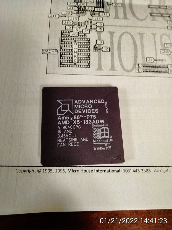
I went superficially through my CPU stack and pulled 2 which should work with it: an IBM 5x86-100 and an AMD 5x86-P75.
This motherboard has a LOT of jumpers. I found a jumper guide at https://www.ultimateretro.net/en/motherboards/5541#downloads but unfortunately that does not have settings specific for the AMD CPU. With patience, I set the jumpers as for an AMD 486DX4, expecting it to work. And of course, I checked them twice, and didn't forget to set the right FSB of 33 and correct voltage. But the motherboard didn't POST when powered up. The CPU is known good, it works in another 486 motherboard. It did get warm while I had the power on.
So I switched to the IBM/Cyrix CPU, and set the jumpers as per the CXM1 in the jumper guide. With that, the motherboard did POST, I could get into the BIOS settings and adjust date/time, other settings etc, save and reboot. Everything looked to be working fine.
But then I attached my usual test drive (a CF card with DOS 6.22 and utilities, the same one I used to test the motherboard in the other thread A nice late socket7 motherboard: PCPartner TXB820DS 35-8333-03 ) and it does not boot. The card is detected correctly by the BIOS detection utility and set as primary drive, etc. But after POST is finished, it locks up when trying to boot. At that point the computer becomes unresponsive, the keyboard has no effect (not even ctrl-alt-del) and I have to turn the power off.
I have gone back in the BIOS and tweaked all I could think of (turned off "block mode" for IDE, turned off 32-bit mode for IDE etc) but it didn't make a difference.
Pics follow:
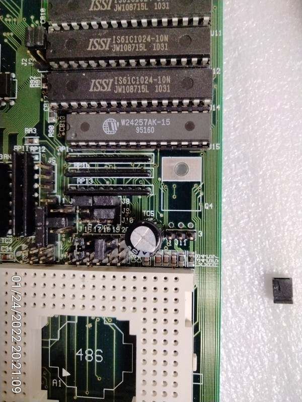
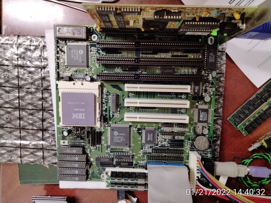
Motherboard with memory, CPU, video card and IDE cable
POST screen
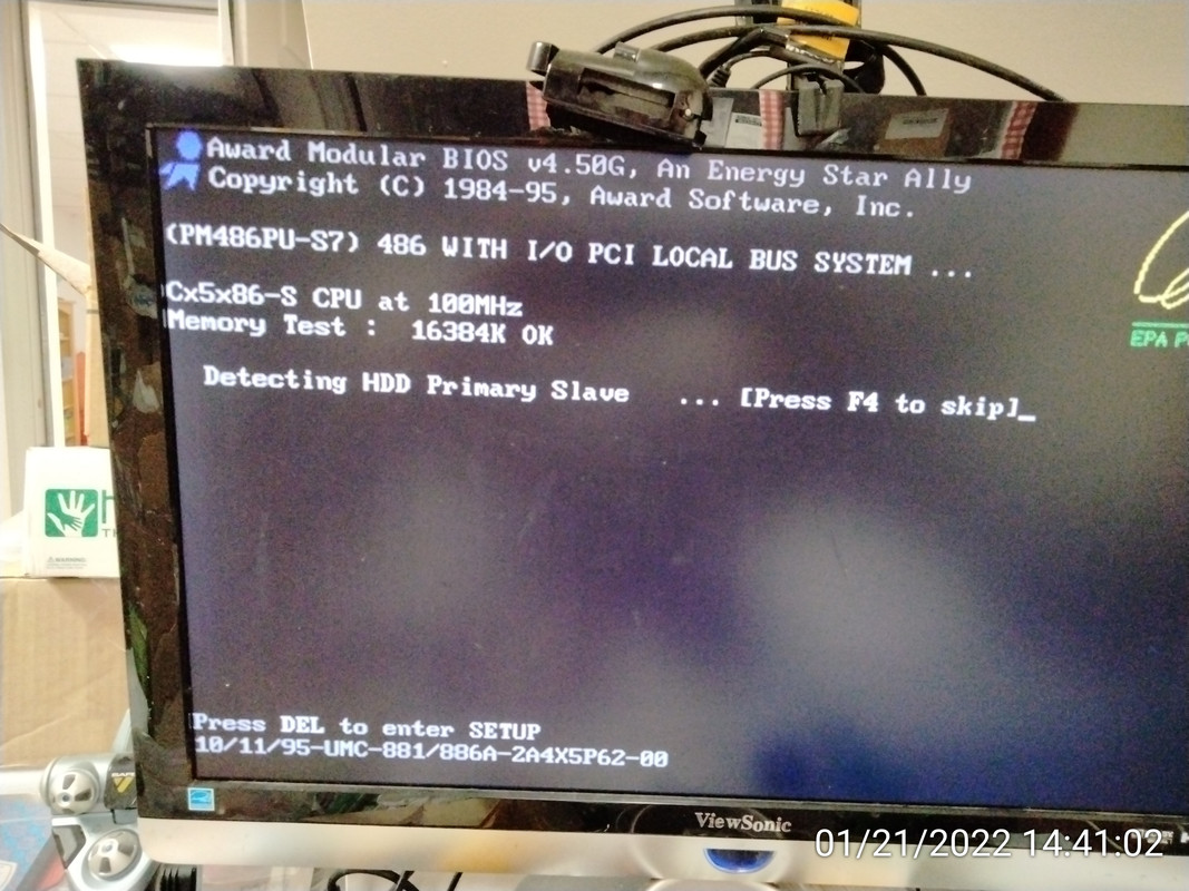
but does not boot
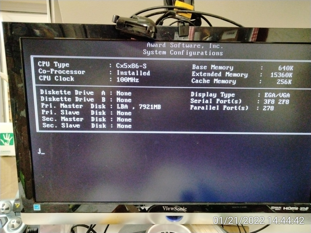
That letter "j" was not typed by me. It appears there automatically without me touching the keyboard. At this point, it does not respond to keyboard anymore.
The CPU that did not POST
If anyone has experience with this motherboard, I'd appreciate the help.
(edit) while I was in the BIOS, I also disabled the CPU cache. It did also not make a difference.
I also noticed that the POST screen says PM486PU-S7 whereas the silkscreen on the motherboard says 486PU-S4. I don't know if it makes a difference. The BIOS string is the same as for the BIOS file available for download at ultimateretro
I/O, I/O,
It's off to disk I go,
With a bit and a byte
And a read and a write,
I/O, I/O