VOGONS


First post, by RogrWilco

User metadata
Rank Newbie
Rank
Newbie

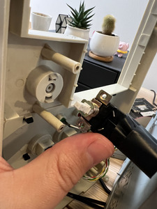
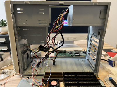
Hi folks. Moved on to the portion of my 486 build where I'm moving the components into the case. I'm wondering if I perhaps don't have a standard AT case? I'm puzzled by how I'm supposed to mount the PSU switch. Please see the attached images. Perhaps this is a non-standard case?

Attachments

  • IMG_0276.jpeg
    Filename
    IMG_0276.jpeg
    File size
    1.02 MiB
    Views
    1016 views
    File license
    Public domain
  • IMG_0277.jpeg
    Filename
    IMG_0277.jpeg
    File size
    1.61 MiB
    Views
    1016 views
    File license
    Public domain

Reply 1 of 13, by kixs

User metadata
Rank l33t
Rank
l33t

I could be wrong. But I always thought the power switch came with the case. Usually the case had already installed PSU.

In your case you will need to modify the switch holder and case holder so the switch will fit and be fixed.

Requests are also possible... /msg kixs

Reply 2 of 13, by debs3759

User metadata
Rank Oldbie
Rank
Oldbie
kixs wrote on 2022-01-22, 22:25:

I could be wrong. But I always thought the power switch came with the case. Usually the case had already installed PSU.

In your case you will need to modify the switch holder and case holder so the switch will fit and be fixed.

With all AT systems I have put together, the switch was supplied attached to the PSU, and they have a standard size fitting. I assumed that to be always true.

See my graphics card database at www.gpuzoo.com
Constantly being worked on. Feel free to message me with any corrections or details of cards you would like me to research and add.

Reply 4 of 13, by BitWrangler

User metadata
Rank l33t++
Rank
l33t++

I have a stash of cheap "metal construction toy" Meccano rip offs for just such occasions, meaning I've got a ready supply of handy bits like... meccanospares.com/6b-ZN-N.html
Even if not the right length you can offset/rotate a bit so looking down on it, it's like a Z

Alternatively I'd look at it and think, hey, if I protected all round with wet paper, maybe I could get a heatgun on those pegs and swerve them in line with the holes..

Or I'd go... hmm, there's just enough metal in the edges of the bracket, maybe I'll slot those holes out and use washers on the screws.

Then if the plunger didn't quite meet, I'd have a choice between jamming an extension peg in the hole in the backside of the button, bending the extension brackets, or jamming something tubular on the plunger.

Should I find the timer ticking, be in git'r'done mode, and have NONE of the above options available, I'd consider using standoffs, or long screws through tubing, drilled through the front of the case.

With still no luck on any of that, I'd dig through the junk electrical and lighting box, find one of those 4 inch "lamp crossbar" pieces and cut and drill that to fit

If I only had crazy glue and baking powder I'd snap off the plastic standoffs, and using modelling clay, or pulped wet tissue, or dough or mud out of the yard to make a "dam" or wall around the base of one where I wanted to reposition it to and fill with layers of crazy glue and baking powder a bit at a time and stirred in until I had a mechanically sound "blob" cementing it to the case front.

Okay I'll shut up now 🤣

Unicorn herding operations are proceeding, but all the totes of hens teeth and barrels of rocking horse poop give them plenty of hiding spots.
Reply 5 of 13, by RogrWilco

User metadata
Rank Newbie
Rank
Newbie
debs3759 wrote on 2022-01-22, 22:46:
kixs wrote on 2022-01-22, 22:25:

I could be wrong. But I always thought the power switch came with the case. Usually the case had already installed PSU.

In your case you will need to modify the switch holder and case holder so the switch will fit and be fixed.

With all AT systems I have put together, the switch was supplied attached to the PSU, and they have a standard size fitting. I assumed that to be always true.

To clarify, this switch is attached to the AT power supply.

Reply 6 of 13, by Plasma

User metadata
Rank Member
Rank
Member

The switch mounts to the metal part of the case not the plastic front panel. Hold it in position behind the round cutout and you should be able to actuate it with the front button. If that works then you just need to drill a couple holes on either side of the cutout, and run screws in from the front into the threaded holes in the switch.

Reply 7 of 13, by RogrWilco

User metadata
Rank Newbie
Rank
Newbie
Plasma wrote on 2022-01-22, 23:34:

The switch mounts to the metal part of the case not the plastic front panel. Hold it in position behind the round cutout and you should be able to actuate it with the front button. If that works then you just need to drill a couple holes on either side of the cutout, and run screws in from the front into the threaded holes in the switch.

If I butt the switch up to the metal there’s not enough room left for the switch to actuate. Might be able to hurry rig something with washers or nuts to create the right distance though. Worth a thought. Thanks!

Reply 8 of 13, by RogrWilco

User metadata
Rank Newbie
Rank
Newbie
BitWrangler wrote on 2022-01-22, 23:21:
I have a stash of cheap "metal construction toy" Meccano rip offs for just such occasions, meaning I've got a ready supply of ha […]
Show full quote

I have a stash of cheap "metal construction toy" Meccano rip offs for just such occasions, meaning I've got a ready supply of handy bits like... meccanospares.com/6b-ZN-N.html
Even if not the right length you can offset/rotate a bit so looking down on it, it's like a Z

Alternatively I'd look at it and think, hey, if I protected all round with wet paper, maybe I could get a heatgun on those pegs and swerve them in line with the holes..

Or I'd go... hmm, there's just enough metal in the edges of the bracket, maybe I'll slot those holes out and use washers on the screws.

Then if the plunger didn't quite meet, I'd have a choice between jamming an extension peg in the hole in the backside of the button, bending the extension brackets, or jamming something tubular on the plunger.

Should I find the timer ticking, be in git'r'done mode, and have NONE of the above options available, I'd consider using standoffs, or long screws through tubing, drilled through the front of the case.

With still no luck on any of that, I'd dig through the junk electrical and lighting box, find one of those 4 inch "lamp crossbar" pieces and cut and drill that to fit

If I only had crazy glue and baking powder I'd snap off the plastic standoffs, and using modelling clay, or pulped wet tissue, or dough or mud out of the yard to make a "dam" or wall around the base of one where I wanted to reposition it to and fill with layers of crazy glue and baking powder a bit at a time and stirred in until I had a mechanically sound "blob" cementing it to the case front.

Okay I'll shut up now 🤣

I love that spirit. I’ll take another look and consider whether any of these would work. Thanks!

Reply 9 of 13, by Plasma

User metadata
Rank Member
Rank
Member
RogrWilco wrote on 2022-01-22, 23:41:
Plasma wrote on 2022-01-22, 23:34:

The switch mounts to the metal part of the case not the plastic front panel. Hold it in position behind the round cutout and you should be able to actuate it with the front button. If that works then you just need to drill a couple holes on either side of the cutout, and run screws in from the front into the threaded holes in the switch.

If I butt the switch up to the metal there’s not enough room left for the switch to actuate. Might be able to hurry rig something with washers or nuts to create the right distance though. Worth a thought. Thanks!

You can also trim the plunger on the switch.

Reply 10 of 13, by RogrWilco

User metadata
Rank Newbie
Rank
Newbie
Plasma wrote on 2022-01-22, 23:45:
RogrWilco wrote on 2022-01-22, 23:41:
Plasma wrote on 2022-01-22, 23:34:

The switch mounts to the metal part of the case not the plastic front panel. Hold it in position behind the round cutout and you should be able to actuate it with the front button. If that works then you just need to drill a couple holes on either side of the cutout, and run screws in from the front into the threaded holes in the switch.

If I butt the switch up to the metal there’s not enough room left for the switch to actuate. Might be able to hurry rig something with washers or nuts to create the right distance though. Worth a thought. Thanks!

You can also trim the plunger on the switch.

Oh I never thought about this! This could work. Will take a look.

Reply 12 of 13, by Plasma

User metadata
Rank Member
Rank
Member

That style switch is fully insulated and designed to be mounted directly to the chassis. The PSU is also grounded to the case, so if there was a short the fuse would blow.

Attachments

  • at_switch.jpg
    Filename
    at_switch.jpg
    File size
    160.04 KiB
    Views
    870 views
    File license
    Public domain

Reply 13 of 13, by RogrWilco

User metadata
Rank Newbie
Rank
Newbie
Plasma wrote on 2022-01-26, 16:28:

That style switch is fully insulated and designed to be mounted directly to the chassis. The PSU is also grounded to the case, so if there was a short the fuse would blow.

This is EXACTLY what I needed to know. Thank you and thanks for the helpful picture!