VOGONS


First post, by ericmackrodt

User metadata
Rank Newbie
Rank
Newbie

Hi Everyone!

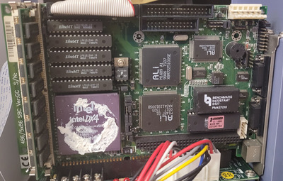
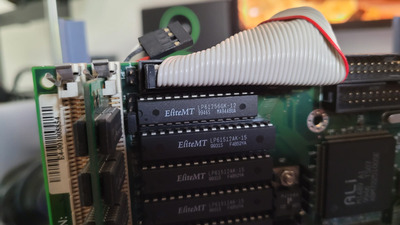
I have an a 486/5x86 SBC, it looks the same as the one from this post here (Re: PC420-G2 Single board computer manual and Troubleshooting).
Mine is not labeled PC420-G2 though, instead it's labeled 486/5x86 SBC Ver:GC.
It seems like it's the exact same one from this site: https://www.empowerlaptop.com/p/486-5x86-sbc- … herboard-w1711/

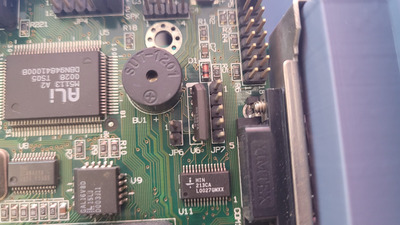
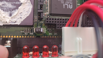
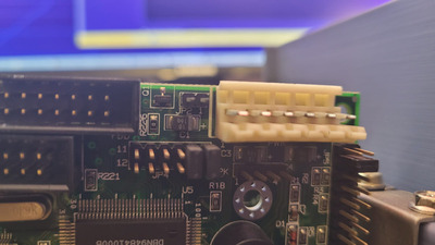
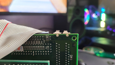
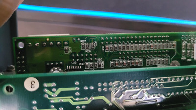
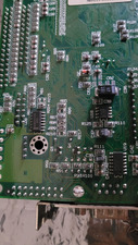
The board works well with the 486 DX4 that came with it but I'm having trouble to find where the front panel LEDs and buttons are connected on it.
I've been searching for a while and I can only find it for other SBCs, I couldn't even find the answer on vogons.

I wonder if anyone has been able to figure out, or maybe has experience with this particular SBC and knows where the front panel stuff is connected.

Thanks in advance for the help.

Reply 2 of 8, by ericmackrodt

User metadata
Rank Newbie
Rank
Newbie

Sorry, I didn't send a photo because the links had it, here's a photo of mine.

20220125_225215.jpg
Filename
20220125_225215.jpg
File size
1.45 MiB
Views
449 views
File license
Public domain
snufkin wrote on 2022-01-25, 11:23:

Any photos of the board?

Reply 4 of 8, by ericmackrodt

User metadata
Rank Newbie
Rank
Newbie

Here we go. I also included jp10.

WhatsApp Image 2022-01-26 at 12.31.45 AM.jpeg
Filename
WhatsApp Image 2022-01-26 at 12.31.45 AM.jpeg
File size
235.65 KiB
Views
428 views
File license
Public domain
WhatsApp Image 2022-01-26 at 12.31.45 AM(1).jpeg
Filename
WhatsApp Image 2022-01-26 at 12.31.45 AM(1).jpeg
File size
182.87 KiB
Views
428 views
File license
Public domain
WhatsApp Image 2022-01-26 at 12.31.45 AM(2).jpeg
Filename
WhatsApp Image 2022-01-26 at 12.31.45 AM(2).jpeg
File size
146.1 KiB
Views
428 views
File license
Public domain
snufkin wrote on 2022-01-25, 12:06:

Thanks. I can't find a manual, but can you get a closer photo showing JP2, JP6 and JP7? They look like a good place to start looking for IDE, Reset and Power/keylock.

Reply 5 of 8, by snufkin

User metadata
Rank Oldbie
Rank
Oldbie

Well, R5 looks like a 150 ohm resistor that connects to pin 1 of JP7, so I think that's a definite possibility for the power LED and keylock: https://old.pinouts.ru/Motherboard/AtLedKeylock_pinout.shtml

If you have a multimeter you can (with the board off) check if there's about 150ohm resistance from pin 1 to a +5 point (pin 11 of those HIN213CA should be at +5v, or maybe pin 4 of the speaker header). Also check if JP7 pin 3 connects to ground.

JP2 looks like pin 2 is connected to ground through Q1 when the via next to the Q1 label goes high. Check where JP2 pin 1 goes. If that also goes to +5 (maybe through a resistor, although the current might be controlled by Q1) then that header sounds like an output of some sort, so might be able to drive an LED. And it's near the drive headers.

Although, I've just noticed a JP1 right next to the HDD header, so that's worth looking at as well.

JP10 looks like at least one pin is pulled high through a 10k resistor, so I'd guess that when it's jumpered that it pulls an input somewhere low (you can check if one pin connects to ground, and the other pin to one of the RP4 pins). Could be anything really, but it should be safe putting a 1k resistor (to keep any currents small) across the pins to see what happens.

I can't see what connects to JP6, but on the grounds that it's near what I think is the power led and keylock, I'd guess that it's front panel related. Check the resistance of both pins to +5 and to Ground.

Reply 6 of 8, by ericmackrodt

User metadata
Rank Newbie
Rank
Newbie

Thanks for the response. I'll try to probe it with my multimeter later tonight.

In the meantime, here's a photo of JP1.

WhatsApp Image 2022-01-26 at 11.24.53 AM.jpeg
Filename
WhatsApp Image 2022-01-26 at 11.24.53 AM.jpeg
File size
156.04 KiB
Views
397 views
File license
Public domain

From the back it does look like it's connected to a resistor:

WhatsApp Image 2022-01-26 at 11.24.54 AM.jpeg
Filename
WhatsApp Image 2022-01-26 at 11.24.54 AM.jpeg
File size
139.32 KiB
Views
397 views
File license
Public domain

JP2 looks like it's connected to R27?

WhatsApp Image 2022-01-26 at 11.24.54 AM(1).jpeg
Filename
WhatsApp Image 2022-01-26 at 11.24.54 AM(1).jpeg
File size
210.12 KiB
Views
397 views
File license
Public domain

This is the area where JP6 and 7 are from the back:

WhatsApp Image 2022-01-26 at 11.24.54 AM(2).jpeg
Filename
WhatsApp Image 2022-01-26 at 11.24.54 AM(2).jpeg
File size
197.16 KiB
Views
397 views
File license
Public domain

I am not sure if JP6 is connected to that transistor or to R91.

snufkin wrote on 2022-01-25, 14:44:
Well, R5 looks like a 150 ohm resistor that connects to pin 1 of JP7, so I think that's a definite possibility for the power LED […]
Show full quote

Well, R5 looks like a 150 ohm resistor that connects to pin 1 of JP7, so I think that's a definite possibility for the power LED and keylock: https://old.pinouts.ru/Motherboard/AtLedKeylock_pinout.shtml

If you have a multimeter you can (with the board off) check if there's about 150ohm resistance from pin 1 to a +5 point (pin 11 of those HIN213CA should be at +5v, or maybe pin 4 of the speaker header). Also check if JP7 pin 3 connects to ground.

JP2 looks like pin 2 is connected to ground through Q1 when the via next to the Q1 label goes high. Check where JP2 pin 1 goes. If that also goes to +5 (maybe through a resistor, although the current might be controlled by Q1) then that header sounds like an output of some sort, so might be able to drive an LED. And it's near the drive headers.

Although, I've just noticed a JP1 right next to the HDD header, so that's worth looking at as well.

JP10 looks like at least one pin is pulled high through a 10k resistor, so I'd guess that when it's jumpered that it pulls an input somewhere low (you can check if one pin connects to ground, and the other pin to one of the RP4 pins). Could be anything really, but it should be safe putting a 1k resistor (to keep any currents small) across the pins to see what happens.

I can't see what connects to JP6, but on the grounds that it's near what I think is the power led and keylock, I'd guess that it's front panel related. Check the resistance of both pins to +5 and to Ground.

Reply 7 of 8, by snufkin

User metadata
Rank Oldbie
Rank
Oldbie

Yeah, J1 goes through R24 (220 ohm), so that could be an LED output. JP2 pin 1 looks like it goes through R27 (330 ohm), with JP2 pin 2 going through Q1 to ground. So could also be an LED output controlled by Q1.

That U6 M51957 next to J6 is some sort of reset controller, and perhaps pin 1 goes up to Q4 pin 3, then across to R93 and ends up connecting to U6 pin 2 (input control). So could be the reset input. Maybe.

Reply 8 of 8, by ericmackrodt

User metadata
Rank Newbie
Rank
Newbie

I will probe it with the multimeter tomorrow and put my findings here.
Thanks for the help!

snufkin wrote on 2022-01-26, 12:00:

Yeah, J1 goes through R24 (220 ohm), so that could be an LED output. JP2 pin 1 looks like it goes through R27 (330 ohm), with JP2 pin 2 going through Q1 to ground. So could also be an LED output controlled by Q1.

That U6 M51957 next to J6 is some sort of reset controller, and perhaps pin 1 goes up to Q4 pin 3, then across to R93 and ends up connecting to U6 pin 2 (input control). So could be the reset input. Maybe.