VOGONS


Strange floppy boot problem

Topic actions

Reply 20 of 33, by Deunan

User metadata
Rank Oldbie
Rank
Oldbie

CR2032 in place of the original NiCD is not that great of an idea, even if it seems to work. There's two problems with this setup:

1) A NiCD has 3.6V nominal voltage, and CR20xx is 3V (about 3.1 to maybe 3.2 when brand new but it drops over time). The mobo has a diode, usually a silicon one with forward drop of some 0.6V at low current, so that during PC uptime the 5V rail is what powers the RTC, not the battery. But that means RTC only sees 3V - 0.6V = ~2.4V or so when PC is turned off. This might not be enough for proper timekeeping and perhaps even CMOS NVRAM content preservation.

2) NiCD is charged, though with a small current, when PSU is running. Unless the mobo has a jumper for non-rechargeable battry option this will result in the CR-type being "charged", which it will not like, not long-term anyway. Might even spill and corrode stuff. Shouldn't catch on fire but you never know with lithium cells.

So a CR20xx will work, or seem to, but it wil not last for long and might even cause trouble. It would be preferable to at least mod the mobo to disable the charging (that's usualy done by removing one resistor), and in general a 3xAAA (or 3xAA) holder will last longer, can be put away from the mobo to prevent any possible spill causing damage, and the AA/AAA cells typically can endure small "charging" current simply due to their size. That's still abuse but usually not resulting in any issues. Might actually re-charge them a bit too.

And a minor issue, the older the mobo the more power-hungry the RTC clock circuit is. This is probably not an issue for this mobo but keep it in mind, the CR20xx will not last long at all on something like early 386 or 286.
Reply 21 of 33, by snufkin

User metadata
Rank Oldbie
Rank
Oldbie

I'm not sure, but I think that most external battery headers have a diode on the +ve pin to stop the external pack from being charged. But that does mean that the voltage drop is even worse, hence using the 3*1.5V cells for the external pack. Datasheets for 82c206 based RTC/CMOS say to use 6V, but then have two diodes on the motherboard, which would drop it to around 5V.

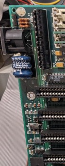
Photos of the front and back of the board showing the area around the battery (corner of the board, to the 3rd or 4th ISA slot, which is where I think the 32kHz oscillator is) might help work out what's needed.

Reply 22 of 33, by EvieSigma

User metadata
Rank Oldbie
Rank
Oldbie

I don't mind using a 3xAA holder, but I'd rather not have to build one if I don't have to.

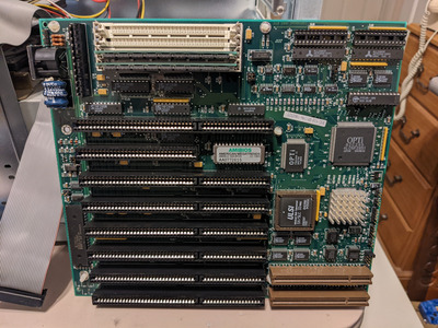
There's a 4 pin header on the other side of the keyboard connector from the (now removed) battery and I assume that's the external battery connector.

PXL_20220129_225051608.jpg
Filename
PXL_20220129_225051608.jpg
File size
1.97 MiB
Views
427 views
File license
CC-BY-4.0

Reply 24 of 33, by snufkin

User metadata
Rank Oldbie
Rank
Oldbie

Good to hear the battery is out. If you can take photos of the front and back of the board showing roughly this area:

BatteryCircuit.jpg
Filename
BatteryCircuit.jpg
File size
19.37 KiB
Views
414 views
File license
Fair use/fair dealing exception

then it should be possible to work out if the necessary diodes are already fitted to the board. I think they are, but would like to make sure. I think pin 1 of the header is normally where the + lead attaches and pin 4 is Ground.

There must be ready made battery holders for this somewhere, but I can't just find them. So it's possible that what you'll need to do is get a 3xAA holder with leads, a 4 pin socket with a couple of female pins (think these get called dupont connectors), put the pins on the leads, put the leads in the socket, and plug the socket on to the header the right way around.

Reply 25 of 33, by Deunan

User metadata
Rank Oldbie
Rank
Oldbie
EvieSigma wrote on 2022-02-01, 15:33:

There's a 4 pin header on the other side of the keyboard connector from the (now removed) battery and I assume that's the external battery connector.

That mobo looks identical to my parts donor, so if the name of that connector is J25 then yes, it's for external battery. Always check which pin is GND, do not rely on numbering and "usual pinout" as some manufacturers had the habit of inverting the pin numbering.

Reply 26 of 33, by Deunan

User metadata
Rank Oldbie
Rank
Oldbie
maxtherabbit wrote on 2022-02-01, 16:03:

buy once cry once, never have to change the batteries again

My 286 mobo would beg to differ 😀 I'm going to upgrade it from 3xAAA to 3xAA because I do not use it much. But on a 386+ system with RTC integrated into '206 chip, or even the main chipset itself, a pack of AAAs should last for many years.

Reply 27 of 33, by EvieSigma

User metadata
Rank Oldbie
Rank
Oldbie
snufkin wrote on 2022-02-01, 16:22:

There must be ready made battery holders for this somewhere, but I can't just find them. So it's possible that what you'll need to do is get a 3xAA holder with leads, a 4 pin socket with a couple of female pins (think these get called dupont connectors), put the pins on the leads, put the leads in the socket, and plug the socket on to the header the right way around.

It looks like I'll have to do that, I don't have any connectors like that but I DO need to order a couple components from Mouser (some capacitors, a 32MHz oscillator) so I might as well order some of those connectors too.

Reply 30 of 33, by darry

User metadata
Rank l33t++
Rank
l33t++
EvieSigma wrote on 2022-02-01, 01:56:

Can you buy CR2032 holders that plug into the external battery header on a motherboard or do you have to build one? I know I've seen some people on YouTube using them.

Something like this https://www.amazon.ca/Casinlog-CR2032-Button- … t/dp/B09BDWJN7Z with a DuPont connector (or soldered directly to battery header) with maybe an inline diode to prevent charging (if necessary) would be practically turnkey as far as I'm concerned .

Optionally, add a blob of hot glue to hold it in place and you're done .

Reply 31 of 33, by Deunan

User metadata
Rank Oldbie
Rank
Oldbie

Eh, I've tried. Sure, go with the CR20xx and add a diode to it as well, see how well that works. I guess some people need to learn from their own mistakes.

Also, I do not understand what needs "building" in a battery holder. Where I live these things come in one piece, with wires, and perhaps even with terminals as well. Look for "BHF-3A3" on Mouser for example, and it's not expensive or anything. How is that more work then having to adapt and glue in a CR20xx holder? I just don't get it.

Reply 32 of 33, by EvieSigma

User metadata
Rank Oldbie
Rank
Oldbie
Deunan wrote on 2022-02-02, 11:21:

Eh, I've tried. Sure, go with the CR20xx and add a diode to it as well, see how well that works. I guess some people need to learn from their own mistakes.

Also, I do not understand what needs "building" in a battery holder. Where I live these things come in one piece, with wires, and perhaps even with terminals as well. Look for "BHF-3A3" on Mouser for example, and it's not expensive or anything. How is that more work then having to adapt and glue in a CR20xx holder? I just don't get it.

Since I've found battery holders with leads, the only thing I need to "build" is whatever you'd call the 4 pin connector on the end to plug into the motherboard, I've never figured out what those are called in order to search for them.

Reply 33 of 33, by snufkin

User metadata
Rank Oldbie
Rank
Oldbie

dupont connectors. Pretty sure I read that they were never actually made by dupont, but that seems to be what they've ended up being called. If you search your nearest massive auction site for "4 pin dupont" it should return loads of results.