First post, by Grayshazzle
Rank
Member
Does anyone have the manual to a Pine BAV693A3PS board, it uses the Apollo 133A chipset. If anyone could find it please let me know. Thank you 😀
Does anyone have the manual to a Pine BAV693A3PS board, it uses the Apollo 133A chipset. If anyone could find it please let me know. Thank you 😀
Pine is one of the many, many PC Chips/ECS/Amptron/HsingTech/Elpina/etc synonyms. This board was also known as PM-V01A-0004.
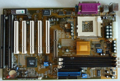
You're also looking for the wrong chipset - Via 693A is the Apollo133 (without A), and the board clearly doesn't have the ApolloPro133A (aka 694X) as it has an AGP 1.0 slot, not 2.0 like the A would have.
So: a full ATX PC Chips board with Via ApolloPro133. Only problem: I can't find one, at least, not one remotely like this board.
What I did find was a different name for what looks like the identical board with a different PCB colour: PM-VK1A-0006 - it was sold under this name by Pine and Eagle. Still no manual though.
But...
What do you actually need the manual for? The dipswitch settings seem excellently documented on the board itself, and there's no onboard stuff beyond the chipset, which determines compatibility/limits. Probably we can figure out anything you are looking for without that manual.
dionb wrote on 2022-02-01, 00:39:Pine is one of the many, many PC Chips/ECS/Amptron/HsingTech/Elpina/etc synonyms. […]
Pine is one of the many, many PC Chips/ECS/Amptron/HsingTech/Elpina/etc synonyms.
You're also looking for the wrong chipset - Via 693A is the Apollo133 (without A), and the board clearly doesn't have the ApolloPro133A (aka 694X) as it has an AGP 1.0 slot, not 2.0 like the A would have.
So: a full ATX PC Chips board with Via ApolloPro133. Only problem: I can't find one, at least, not one remotely like this board.
What I did find was a different name for what looks like the identical board with a different PCB colour: PM-VK1A-0006 - it was sold under this name by Pine and Eagle.
But...
What do you actually need the manual for? The dipswitch settings seem excellently documented on the board itself, and there's no onboard stuff beyond the chipset, which determines compatibility/limits. Probably we can figure out anything you are looking for without that manual.
So now that you mention it, the only thing I actually am looking for is the documentation for led headers. I was told keylock can get the power led working, I just don't know which pins would activate that and the spacing needed for what is positive and negative. The HDD led header on this board too is 4 pins while most today are just 2 pins so I am not sure (motherboards back then varied a lot it seemed, not standardized). I will post a pic below of my mb headers. Thank you.
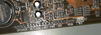
Pin 1 seems clearly indicated, that would be where to put the (green) coloured wire for HDD LED, the other would go onto one of the other three. I'd guess all three would be wired to GND, so 2, 3 or 4 pin connectors would all work. Failing that, just separate the connector and try the options one by one.
Power LED is just a continuous 5V signal, which you can pick up from anywhere on the board with +5VDC, but here again pin 1 for PWR seems pretty clearly indicated. Red goes there, black on the other one.
Not sure a manual would help you here, generally what is already printed on the motherboard is the best you can expect. One of my petty peeves about motherboard manuals - they often excruciatingly extensively document completely standard things (ATX pinout, IDE pinout etc) while glossing over or downright ignoring the relevant bits that are actually unique to the board.
dionb wrote on 2022-02-01, 08:11:Pin 1 seems clearly indicated, that would be where to put the (green) coloured wire for HDD LED, the other would go onto one of the other three. I'd guess all three would be wired to GND, so 2, 3 or 4 pin connectors would all work. Failing that, just separate the connector and try the options one by one.
Power LED is just a continuous 5V signal, which you can pick up from anywhere on the board with +5VDC, but here again pin 1 for PWR seems pretty clearly indicated. Red goes there, black on the other one.
Not sure a manual would help you here, generally what is already printed on the motherboard is the best you can expect. One of my petty peeves about motherboard manuals - they often excruciatingly extensively document completely standard things (ATX pinout, IDE pinout etc) while glossing over or downright ignoring the relevant bits that are actually unique to the board.
Awesome, thank you so much. So funny because last night after this post I realized that the 1 does indicate the first pin and I didn't know. Also viewing pinouts for each header really helps! Thank you 🙂👍
dionb wrote on 2022-02-01, 20:13:Little mess-up on my part this morning (didn't sleep well, I'll blame that) - "PWR" isn't the power LED but the power button (which doesn't care about polarity).
You can definitely use KEYLOCK for power LED, pin 1 is 5V, pin 2 GND, see: here
No worries, thank you very much 😀
