VOGONS


First post, by RaiderOfLostVoodoo

User metadata
Rank Member
Rank
Member

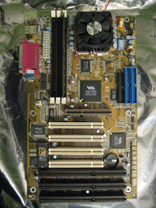
The board in question:
wwtF9k7.jpg
DFI K6XV3+/66 Rev:B2
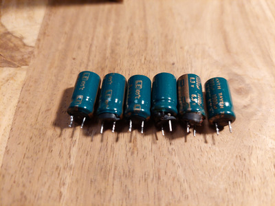
My buddy Hirsch changed the capacitors with polymer caps from Kemet and Nichicon.

After the recapping my board can no longer boot into WinXP if I run my K6-2/500AFX at stock voltage (2.2V). However it can boot into Win98, but I assume it would eventually crash. Overvolting the CPU to 2.4V doesn't change anything. It still freezes during WinXP boot.
If I downclock it to 100MHz*4.5, I can boot into WinXP. I can even downvolt to 1.55V. At 1.5V it crashes during boot and restarts.

My K6-III+/400ATZ also behaves strangely. It can run at the stock voltage (1.6V). At 1.7V I can even overclock it to 100MHz*5.5, but after that I do hit a wall. I can't get 100MHz*6 stable. Not even at 2.4V. 41% overvoltage not enough for 9% overclock? This can't be!

I assume the board can't deliver more than 1.8V or something like that. I can't measure the voltage, because I don't have equipment for that. Gonna have to wait until Hirsch is in the area again (probably around Easter I guess).
We suspect that a loose soldering point might cause the issues. But which capacitor? Resoldering them all takes way too long.
Any advice?

Reply 1 of 13, by rasz_pl

User metadata
Rank l33t
Rank
l33t

>Any advice?

-dont waste money on mythical audiophool recaps
-Use oscilloscope to look at the Vcore ripple, used controller might expect some ESR and not work properly without it
-stop polishing turds. I get that you had AMD K6 in the nineties (parents got scammed, didnt want to or couldnt pay more), but that doesnt mean you cant have a good retro computer today 😀

Open Source AT&T Globalyst/NCR/FIC 486-GAC-2 proprietary Cache Module reproduction

Reply 2 of 13, by RaiderOfLostVoodoo

User metadata
Rank Member
Rank
Member
rasz_pl wrote on 2022-02-22, 12:32:

-stop polishing turds. I get that you had AMD K6 in the nineties (parents got scammed, didnt want to or couldnt pay more), but that doesnt mean you cant have a good retro computer today 😀

No, I didn't have a K6 in the 90s.
You don't seem to know that K6's are actually more valuable than Pentium II's now, because of flexibility (downclocking for speed sensitive games).

Reply 3 of 13, by stamasd

User metadata
Rank l33t
Rank
l33t

I assume you did install a CMOS battery. The picture doesn't show one. If you didn't, that would be the first thing to do. 😀
I will also assume that you don't have an oscilloscope, since you don't even have a way to measure voltages. Get a multimeter, you can find decent ones for probably 10-15 euro. You can't hope to begin troubleshooting electrical problems without one.
Retouching the caps solder points shouldn't take too long, even done blindly for all of them. About 5-10 seconds per solder point, you should be done in 15-20min.

I/O, I/O,
It's off to disk I go,
With a bit and a byte
And a read and a write,
I/O, I/O

Reply 4 of 13, by RaiderOfLostVoodoo

User metadata
Rank Member
Rank
Member
stamasd wrote on 2022-02-22, 12:49:

I assume you did install a CMOS battery. The picture doesn't show one.

Yes of course. I usually store boards without battery and only insert it if I use them.

stamasd wrote on 2022-02-22, 12:49:

I will also assume that you don't have an oscilloscope, since you don't even have a way to measure voltages. Get a multimeter, you can find decent ones for probably 10-15 euro. You can't hope to begin troubleshooting electrical problems without one.

As I said, my buddy Hirsch got a good multimeter.
Not sure if he has an oscilloscope.

Reply 5 of 13, by Deunan

User metadata
Rank Oldbie
Rank
Oldbie

While polymer electrolytics are great, I think it was a bit overkill to recap entire mobo of this generation with them. But that surely wouldn't make thing worse, if done right. So yes, it could be soldering issue - but to assume it has to be the CPU voltage problem without even one single measurement is rather silly.

I would first run a decent memory test, like memtest86, leave it overnight if needed so it can do several passes on warmed-up mobo. It could be RAM issues, cache issues, or even just too aggresive timings set in BIOS. I'd start with that before blindly resoldering everyting again.

Reply 6 of 13, by RaiderOfLostVoodoo

User metadata
Rank Member
Rank
Member
Deunan wrote on 2022-02-22, 14:42:

While polymer electrolytics are great, I think it was a bit overkill to recap entire mobo of this generation with them.

Well, we don't want to bother with caps ever again, so we're recapping the boards which we intend to use in our rigs with polymer caps.

Deunan wrote on 2022-02-22, 14:42:

I would first run a decent memory test, like memtest86, leave it overnight if needed so it can do several passes on warmed-up mobo. It could be RAM issues, cache issues, or even just too aggresive timings set in BIOS. I'd start with that before blindly resoldering everyting again.

It's not the RAM. Disabling onboard cache doesn't change anything. It's also not the CPU. It runs fine on my other K6XV+/66, which isn't recapped yet.
Nothing was changed, except the caps. So the problem is definitely related to the recapping process.

Reply 7 of 13, by ciornyi

User metadata
Rank Member
Rank
Member

Did you replace same capacity ? As i heard polymer capacitors have to be 2-3 times lower than electronic

DOS: 166mmx/16mb/Y719/S3virge
DOS/95: PII333/128mb/AWE64/TNT2M64
Win98: P3_900/256mb/SB live/3dfx V3
Win Me: Athlon 1700+/512mb/Audigy2/Geforce 3Ti200
Win XP: E8600/4096mb/SB X-fi/HD6850

Reply 8 of 13, by Deunan

User metadata
Rank Oldbie
Rank
Oldbie
RaiderOfLostVoodoo wrote on 2022-02-22, 15:01:

It's not the RAM. Disabling onboard cache doesn't change anything. It's also not the CPU. It runs fine on my other K6XV+/66, which isn't recapped yet.
Nothing was changed, except the caps. So the problem is definitely related to the recapping process.

Well, in that case it could be down to a bad solder connection, especially near the CPU socket. I just hope you didn't damage, or even rip out, any vias when removing the old caps. These PCBs have so many power and GND planes inside them that without pre-heating the board it's difficult to properly (de)solder anything on them.

I would test it this way: Set the motherboard on some table, upright (standing on edge), make sure you have free access to the back side. Install CPU only (with cooling), memory stick and nothing else. Connect to power supply and power up. Now connect one lead of the volt meter to the GND (you can just stick it into a free AMP plug for HDD), and with the other lead test the (+) side of each capacitor you replaced. Note down the voltage. Be SUPER careful not to short anything while probing - steady hands, and elbows support.

The voltages should all be either from PSU (so the usual 5V, 12V, -5V, -12V) or the CPU/DIMM regulators (3.3V and whatever was set for CPU core). Note that negative voltages will have the (+) connected to GND and (-) is actually where the voltage should be measured. Any other value and you most likely have a poor solder joint or a broken via, possibly broken in the internal layers. This can sometimes be fixed too, by running wires to whatever voltage source should be there. Good luck.

Reply 9 of 13, by Hirsch

User metadata
Rank Newbie
Rank
Newbie
ciornyi wrote on 2022-02-22, 17:17:

Did you replace same capacity ? As i heard polymer capacitors have to be 2-3 times lower than electronic

I replaced the same capacity. Since I recapped a second DFI K6XV+/66 for myself with exactly the same caps (even from the same Mouser order) I'm absolutely sure that it's not a problem with capacity. The second board works like a charm.

Deunan wrote on 2022-02-22, 18:12:

Well, in that case it could be down to a bad solder connection, especially near the CPU socket. I just hope you didn't damage, or even rip out, any vias when removing the old caps. These PCBs have so many power and GND planes inside them that without pre-heating the board it's difficult to properly (de)solder anything on them.

In oder to prevent damage on the vias I add some leaded solder first (lowers the melting point) and then I heat up both wires of the cap the *same time* with a bigger iron and pull the cap *straight ahead* with low force once the solder is molten. (Straight ahead is important, otherwise vias might be damaged.) When desoldering something with more than two wires I use hot air.

For me it sounds that the production of VCore does not work properly. I marked the measuring point with a red rectangle for the case you get hands on a multimeter before we meet again. (Two wires between the caps vs. GND.) Directly after the recapping I made a successful memtest86+ run wihout changing VCore or the CPU. I've got two suspicions:
- A small crumb of solder rest found its way somewhere. --> Brush off back side of mainboard carefully with a soft and antistatic brush.
- RaiderOfLostVoodoo cleaned the mainboard under running water after the recap. Perhaps some dirt got into the dip switches so that some of them don't make proper contact. (Matches with the observation that some VCore settings seem to work and others don't.) --> Measure VCore for different dip settings and replace dip switch in case of weird measurements.

RaiderOfLostVoodoo wrote on 2022-02-22, 13:42:

Not sure if he has an oscilloscope.

I've got a very cheap one of Velleman for PC USB connection going just up to 1 MHz. I bought this in order to get familiar with oscilloscope usage before spending more money for a proper one from Agilent.

Deunan wrote on 2022-02-22, 18:12:

I would test it this way: Set the motherboard on some table, upright (standing on edge), make sure you have free access to the back side. Install CPU only (with cooling), memory stick and nothing else. Connect to power supply and power up. Now connect one lead of the volt meter to the GND (you can just stick it into a free AMP plug for HDD), and with the other lead test the (+) side of each capacitor you replaced. Note down the voltage. Be SUPER careful not to short anything while probing - steady hands, and elbows support.

The voltages should all be either from PSU (so the usual 5V, 12V, -5V, -12V) or the CPU/DIMM regulators (3.3V and whatever was set for CPU core). Note that negative voltages will have the (+) connected to GND and (-) is actually where the voltage should be measured. Any other value and you most likely have a poor solder joint or a broken via, possibly broken in the internal layers. This can sometimes be fixed too, by running wires to whatever voltage source should be there. Good luck.

Very good idea. We'll check this after checking the DIP switches. In doubt we might compare with the not recapped mainboard.

Attachments

  • wwtF9k7.jpg
    Filename
    wwtF9k7.jpg
    File size
    1.1 MiB
    Views
    764 views
    File license
    Public domain

Reply 11 of 13, by quicknick

User metadata
Rank Oldbie
Rank
Oldbie

Oh, those are special ultra-low-esr caps, even polymers cannot match that 🤣

If the recapped boards are identical, down to the hardware revision # and the vrm controller being used, and assuming nothing bad happened during the recap, maybe the problems could be caused by water still remaining inside DIP switches or somewhere else (under chipset etc.)?

Reply 12 of 13, by Deunan

User metadata
Rank Oldbie
Rank
Oldbie
Hirsch wrote on 2022-02-22, 21:49:

RaiderOfLostVoodoo cleaned the mainboard under running water after the recap. Perhaps some dirt got into the dip switches so that some of them don't make proper contact.

Well that would be easy to fix, work the switches back and forth a couple of times, this usually cleans the contacts. If not, pour some 99% IPA on it and repeat the process. Hell, even strong vodka might do the trick.

Reply 13 of 13, by RaiderOfLostVoodoo

User metadata
Rank Member
Rank
Member
quicknick wrote on 2022-02-22, 22:43:

If the recapped boards are identical, down to the hardware revision # and the vrm controller being used...

All our boards (we both have 1 modded, 1 untouched and 1 broken one) are Rev:B2 I think.
But the chips slightly different: Cache, BIOS and other where I don't know what they do.
Where is the VRM controller located? Top right?

Would be interesting to see how my K6-2/500AFX behaves on Hirschs recapped board.

quicknick wrote on 2022-02-22, 22:43:

...maybe the problems could be caused by water still remaining inside DIP switches or somewhere else (under chipset etc.)?

Unlikely. I always dry them in the oven for a few hours.
And of course I remove the battery and let them sit for a day, to make sure there is no charge left.