VOGONS


First post, by subnet_zero

User metadata
Rank Newbie
Rank
Newbie

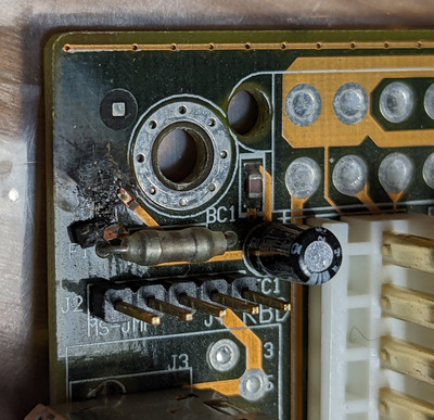
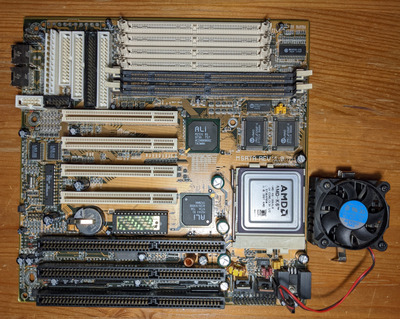
hi, I totally forgot about this M5ATA board in the basement. It has the L1 inductor(?) blown, next to the AT power connector an the fuse F1. First, It seems the damage was done because someone put in the AT power plug the wrong way round.
But then I poked around an the connection goes to PIN 4 of the PS/2 connector. Pin 4 is +5VDC output. Maybe this was blown because something draws to much power?

From pictures in the web, this was an SMD inductor. If anyone knows what value this inductor had, it would be great. I have not much hope, because regular multimeter an not measure Henry.

I'm thinking of repairing this board by bridging this inductor and go without it. What do you think? (I know a circuit diagram would be better, I will figure out the connection of the different parts later.)

Attachments

  • Biostar_M5ATA_L1_blown.jpg
    Filename
    Biostar_M5ATA_L1_blown.jpg
    File size
    790.97 KiB
    Views
    485 views
    File comment
    Blown inductor L1
    File license
    Public domain
  • Biostar_M5ATA.jpg
    Filename
    Biostar_M5ATA.jpg
    File size
    2 MiB
    Views
    485 views
    File comment
    Biostar M5ATA full board
    File license
    Public domain

Reply 1 of 5, by Horun

User metadata
Rank l33t++
Rank
l33t++

From memory they are typically between 1-4uH, usually at least 2 (clock and data) for each the KB and mouse, some older AT boards had 3 or 4.
They are noise suppressors and you could probably get by without one as a test or rob a old dead mobo of one....some used just a wire thru a ferrite bead....

Hate posting a reply and then have to edit it because it made no sense 😁 First computer was an IBM 3270 workstation with CGA monitor. Stuff: https://archive.org/details/@horun

Reply 2 of 5, by subnet_zero

User metadata
Rank Newbie
Rank
Newbie

Thanks. I did some measurement with the multimeter: From AT Connector +5VDC is going to F1 (Fuse) then to L1 (blown) to BC1 (SMD cap) then to GND, then to the bigger cap TC1 (25V 10µF) and also to Pin4 for PS/2 +5VCD. I can't figure it out properly atm. 😓 (Maybe BC1 and TC1 are caps in parallel to GND...🤔)
I will replacing L1 with a wire an see if I get away with it. I'm happy that this seems to be the only damage on the board. 😅

Reply 3 of 5, by snufkin

User metadata
Rank Oldbie
Rank
Oldbie

Might be worth checking if those surface mount capacitors have gone short. Something must have caused the inductor to blow, and a shorted capacitor might cause that. And then the inductor blew in time to save the fuse. If there is a short then putting a wire in will probably (hopefully) blow the fuse.

Reply 4 of 5, by subnet_zero

User metadata
Rank Newbie
Rank
Newbie
snufkin wrote on 2022-03-07, 20:47:

Might be worth checking if those surface mount capacitors have gone short. Something must have caused the inductor to blow, and a shorted capacitor might cause that. And then the inductor blew in time to save the fuse. If there is a short then putting a wire in will probably (hopefully) blow the fuse.

Thanks mentioning this. I've checked all caps an resistor around this side and every big one on the board. Nothing seems wrong.
I also found an L2 named resistor with 4R7 (5 Ohms) marking on the other side of the board. Seems this planned inductor was replaced with a resistor...can't find any other SMD inductor on the board.

Horun wrote on 2022-03-06, 00:15:

From memory they are typically between 1-4uH, usually at least 2 (clock and data) for each the KB and mouse, some older AT boards had 3 or 4.
They are noise suppressors and you could probably get by without one as a test or rob a old dead mobo of one....some used just a wire thru a ferrite bead....

This missing inductor was not connected to clock and data, only +5VDC.