VOGONS


Reply 40 of 115, by Sphere478

User metadata
Rank l33t++
Rank
l33t++
New Bitmap image.png
Filename
New Bitmap image.png
File size
446.73 KiB
Views
1103 views
File license
Public domain

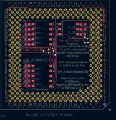
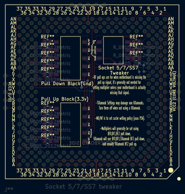
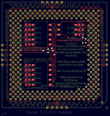
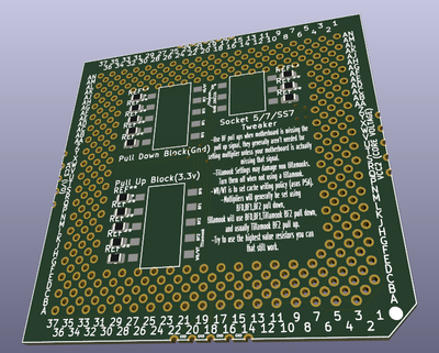
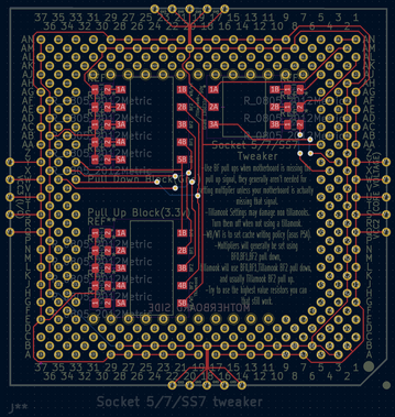
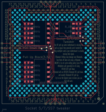
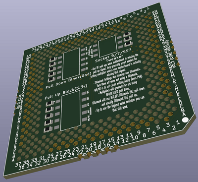
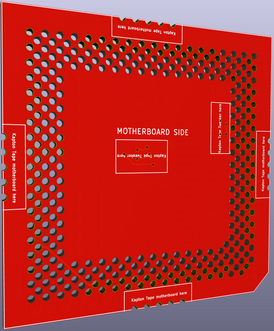
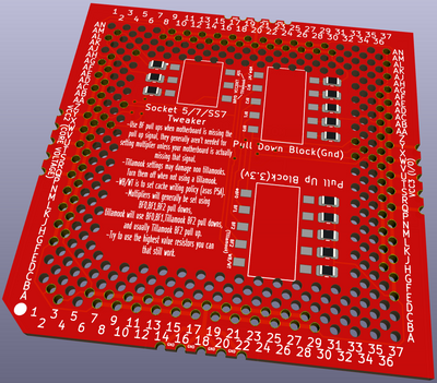
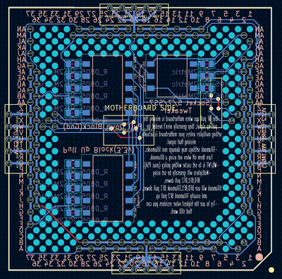
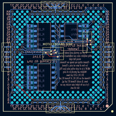
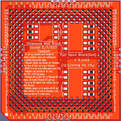
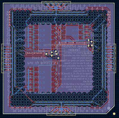
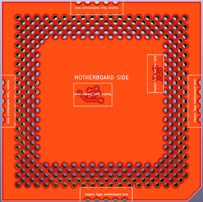
did some silk screen

here are the latest files

Filename
socket7-mod.zip
File size
1.17 MiB
Downloads
46 downloads
File license
Public domain

I was kinda wanting to add a multiplier table

but there are so many different configurations that don't match all cpus

I need to collect info from all the cpus in my collection in order to make a universal table
and I'm not quite sure how to format it

perhaps like this?

bf0,1,2

1=pull down 0=pull up

p54c p55c tillamook k6 k6-2/3/+ mp6 6x86 MII winchip
1x na na na na na na 101
1.5
2x na
2.5x
3x
3.5x
4x 001
4.5x
5x
5.5x 001
6x 100

^can only view in full screen in desktop window.
etc....

or
1x off off on
1.5x off off off
1.75x on on off
2.0x on off off
2.33x off on on
2.5x on on off
2.66x off off on
3.0x off on off
3.33x on off off
3.5x off off off
4.0x on off on
4.5x on on on
5.0x off on on
5.5x off off on
6.0x on off off

as per this link https://www.pchardwarelinks.com/cpuspeed.htm

"Notes:
The AMD K5 has multipliers of 1.5x, 1.75x, and 2.0x. Setting the motherboard to 1.5x or 2.0x will be interpreted by the processor as a 1.5x multiplier. 2.5x is interpreted as 1.75x, and 3.0x becomes 2.0x. This varies depending on the model of the chip. See below for which chips have what multipliers.
The AMD K6 233 and the Pentium MMX 233 interpret a 1.5x multiplier as 3.5x. 233MHz is the maximum limit for the Intel chip since it does not have a multiplier higher than 3.5x.
The Model 8 K6-2 CXT, Model 9 K6-3, and Model D K6-2+ and K6-III+ are the only Socket 7 chips with a 6.0x multiplier (it takes the place of the 2.0x multiplier).
For 4.0x and higher multipliers on the K6, there must be a jumper on the motherboard to set pin BF2 or the chip will default to 'Pulled High', and only give a maximum of 3.5x multiplier. BTW, the AMD K6 does not have a 1.5x multiplier at all.
The IDT (Centaur) Winchip and Winchip-2 do not have fractional multipliers. The normal 2.5x setting is defined as 'reserved', and the 1.5x setting is interpreted by the chip as 4.0x. When BF2 is added to the motherboard, the typical settings for 4.5x and 5.5x are 'reserved'. 4.0x and 5.0x are unchanged.
The IDT (Centaur) Winchip-2A adds the unusual 2.33x and 2.66x multipliers in place of the 5.0x and 5.5x settings.
Default multiplier settings (If the chip receives no signal on its multipliers pins (they're left 'floating'), it reverts to its default setting.):
AMD K5 - 1.5x
AMD K6/K6-2/K6-3/K6-2+/K6-III+ - 3.5x
Cyrix/IBM 6x86/6x86L/6x86MX/M-II - 2.0x
Cyrix M-II (later versions w/ CLKMUL2) - 3.0x
IDT (Centaur) Winchip/Winchip-2/Winchip-2B - 4.0x
IDT (Centaur) Winchip-2A/Winchip-3 - 3.5x
Intel Pentium Classic - 1.5x
Intel Pentium w/ MMX - 2.0x
Rise mP6 - 2.0x"

but it's bound to not apply to all cpus, seems like a table is the best way. but it will be a huge table!

Anyway, I don’t think there is enough room for it unless we make a break away tab on the side of the board.

it will be quite a project confirming all the settings also... even then it will still have errors/gaps because for example intel locked pentiums, same s spec number chips can respond to settings differently

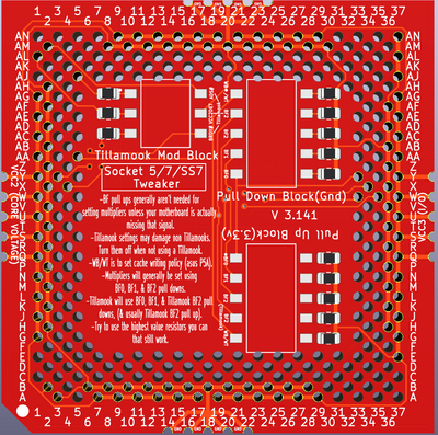
honestly, probably the easiest thing to say is:
use BF pull ups if missing/needed. otherwise multipliers will be set via pull down on BF0, BF1, and (BF2 or Tillamook BF2) try these combos on pull down and see what you get:
000
100
010
110
001
101
011
111

Sphere's PCB projects.
-
Sphere’s socket 5/7 cpu collection.
-
SUCCESSFUL K6-2+ to K6-3+ Full Cache Enable Mod
-
Tyan S1564S to S1564D single to dual processor conversion (also s1563 and s1562)

Reply 41 of 115, by Sphere478

User metadata
Rank l33t++
Rank
l33t++

latest

Filename
socket7-mod.zip
File size
894.55 KiB
Downloads
43 downloads
File license
Public domain

zip

spaint.png
Filename
spaint.png
File size
215.78 KiB
Views
1057 views
File license
Public domain

it may be possible to make a vrm module that surrounds the adapter, one could remove the fets on the motherboard and use the adapter that went around the socket to supply power maybe. won't be able to give socket 5 dual plane but it could give socket 7 more voltage options. ultimately I think this project will evolve into a powerleap style project.

Attachments

  • spaint.png
    Filename
    spaint.png
    File size
    334.94 KiB
    Views
    1057 views
    File license
    Public domain

Sphere's PCB projects.
-
Sphere’s socket 5/7 cpu collection.
-
SUCCESSFUL K6-2+ to K6-3+ Full Cache Enable Mod
-
Tyan S1564S to S1564D single to dual processor conversion (also s1563 and s1562)

Reply 42 of 115, by Sphere478

User metadata
Rank l33t++
Rank
l33t++
Filename
socket7-mod.zip
File size
1.05 MiB
Downloads
44 downloads
File license
Public domain

added back some missing pins, connected a few stray voltage pins, moved some traces.

Attachments

  • New Bitmap image.png
    Filename
    New Bitmap image.png
    File size
    185.37 KiB
    Views
    1042 views
    File license
    Public domain
  • preview.png
    Filename
    preview.png
    File size
    297.56 KiB
    Views
    1046 views
    File license
    Public domain

Sphere's PCB projects.
-
Sphere’s socket 5/7 cpu collection.
-
SUCCESSFUL K6-2+ to K6-3+ Full Cache Enable Mod
-
Tyan S1564S to S1564D single to dual processor conversion (also s1563 and s1562)

Reply 43 of 115, by Sphere478

User metadata
Rank l33t++
Rank
l33t++
Filename
socket7-mod.zip
File size
1.72 MiB
Downloads
44 downloads
File license
Public domain

I think I got the holes resized right?

Attachments

  • preview.png
    Filename
    preview.png
    File size
    544.88 KiB
    Views
    1036 views
    File license
    Public domain
  • New Bitmap image.png
    Filename
    New Bitmap image.png
    File size
    490.05 KiB
    Views
    1036 views
    File license
    Public domain

Sphere's PCB projects.
-
Sphere’s socket 5/7 cpu collection.
-
SUCCESSFUL K6-2+ to K6-3+ Full Cache Enable Mod
-
Tyan S1564S to S1564D single to dual processor conversion (also s1563 and s1562)

Reply 45 of 115, by Sphere478

User metadata
Rank l33t++
Rank
l33t++
Kahenraz wrote on 2022-03-30, 16:12:

I assume that this is the kind of kit that you solder onto the pins?

on the back of the motherboard

----------------------------

I noticed a while back the orientation seems to backwards.. might have to copy the top layer to the bottom and bottom to the top

not quite sure how to do that yet...

Sphere's PCB projects.
-
Sphere’s socket 5/7 cpu collection.
-
SUCCESSFUL K6-2+ to K6-3+ Full Cache Enable Mod
-
Tyan S1564S to S1564D single to dual processor conversion (also s1563 and s1562)

Reply 47 of 115, by Sphere478

User metadata
Rank l33t++
Rank
l33t++

Anyone able to figure out how to mirror image the pcb?

Right now it’s got the pads on the mobo side 🤣

Guess I should have double checked reading back I see wiretap thought it went on the front somehow. I kinda just kept going on the side that the switches were on

Sphere's PCB projects.
-
Sphere’s socket 5/7 cpu collection.
-
SUCCESSFUL K6-2+ to K6-3+ Full Cache Enable Mod
-
Tyan S1564S to S1564D single to dual processor conversion (also s1563 and s1562)

Reply 48 of 115, by Doornkaat

User metadata
Rank l33t
Rank
l33t

Hey, congrats on going all in on this! 😃👍
I feel like this is going to be a labour of love and a really nice device.😁

One quick feedback: Some boards, especially Super7, have a through hole thermal sensor in the middle of the socket. Maybe it would make sense to leave an area in the center free of traces to be able to drill out a hole if required.

Reply 50 of 115, by Sphere478

User metadata
Rank l33t++
Rank
l33t++
Filename
Socket 5-7-SS7 Tweaker.zip
File size
1.26 MiB
Downloads
45 downloads
File license
Public domain

okay, I need to error check this (help me out if you would, do you guys see any mistakes?)

It's starting to look like a viable beta
-did some more silk screen

-flipped the orientation (PIA)

-tweaked a few things here and there

lookin better!

New Bitmap image - Copy.png
Filename
New Bitmap image - Copy.png
File size
303.21 KiB
Views
955 views
File license
Public domain
New Bitmap image.png
Filename
New Bitmap image.png
File size
393.96 KiB
Views
955 views
File license
Public domain
preview.png
Filename
preview.png
File size
114.92 KiB
Views
955 views
File license
Public domain

Sphere's PCB projects.
-
Sphere’s socket 5/7 cpu collection.
-
SUCCESSFUL K6-2+ to K6-3+ Full Cache Enable Mod
-
Tyan S1564S to S1564D single to dual processor conversion (also s1563 and s1562)

Reply 51 of 115, by Sphere478

User metadata
Rank l33t++
Rank
l33t++

okay version 3.141!,

Filename
Socket 5-7-SS7 Tweaker 3.141.zip
File size
1.43 MiB
Downloads
41 downloads
File license
Public domain

-noticed a missing key pin hole - fixed
-tweaked the traces a little more
-messed with writing on silk screen
-various other small fixes

everything looks right far as I can see... double check me here Vogonians!

Front 3D.png
Filename
Front 3D.png
File size
368.95 KiB
Views
931 views
File license
Public domain
Schematic.png
Filename
Schematic.png
File size
121.46 KiB
Views
931 views
File license
Public domain
Back 3D.png
Filename
Back 3D.png
File size
321.06 KiB
Views
931 views
File license
Public domain

Sphere's PCB projects.
-
Sphere’s socket 5/7 cpu collection.
-
SUCCESSFUL K6-2+ to K6-3+ Full Cache Enable Mod
-
Tyan S1564S to S1564D single to dual processor conversion (also s1563 and s1562)

Reply 52 of 115, by debs3759

User metadata
Rank Oldbie
Rank
Oldbie

I said it on discord, but will say it here as well. I think an interposer would be much more useful to most potential users than a board that has to be aligned with the very short pins on the rear of the motherboard and soldered in place. I'm not even sure how most users could solder it to the pins on the back of the board?

See my graphics card database at www.gpuzoo.com
Constantly being worked on. Feel free to message me with any corrections or details of cards you would like me to research and add.

Reply 53 of 115, by Kahenraz

User metadata
Rank l33t
Rank
l33t

I think the use case is different. I like the idea of being able to do all of the modifications to the board and then be able to easily swap chips with without dealing with an interposer.

What did you have in mind? Something that is soldered to the CPU or a little board with a ZIF socket on it. How would we even manufacturer something with CPU pins on it? And ZIF sockets will be expensive and difficult to source.

Reply 54 of 115, by debs3759

User metadata
Rank Oldbie
Rank
Oldbie
Kahenraz wrote on 2022-03-31, 17:00:

I think the use case is different. I like the idea of being able to do all of the modifications to the board and then be able to easily swap chips with without dealing with an interposer.

What did you have in mind? Something that is soldered to the CPU or a little board with a ZIF socket on it. How would we even manufacturer something with CPU pins on it? And ZIF sockets will be expensive and difficult to source.

A socket type interposer, like what was used back in the day for some uses. Something that can be used for different boards and CPUs. I don't know many people who could solder hundreds of contacts on a motherboard, more so when those contacts are between the motherboard and the board being soldered to it.

See my graphics card database at www.gpuzoo.com
Constantly being worked on. Feel free to message me with any corrections or details of cards you would like me to research and add.

Reply 55 of 115, by Sphere478

User metadata
Rank l33t++
Rank
l33t++

v 3.1415

Filename
Socket 5-7-SS7 Tweaker 3.1415.zip
File size
1.58 MiB
Downloads
46 downloads
File license
Public domain

-added flood planes to help with EMI (also they look cool)
-tweaked the silk screen some more
-corrected some tracing errors
-added more info

need to figure out how to attach the floods to specific vias/traces still

Front 3D.png
Filename
Front 3D.png
File size
407.7 KiB
Views
885 views
File license
Public domain
Schematic.png
Filename
Schematic.png
File size
109.13 KiB
Views
885 views
File license
Public domain
Back 3D.png
Filename
Back 3D.png
File size
286.8 KiB
Views
885 views
File license
Public domain
debs3759 wrote on 2022-03-31, 15:59:

I said it on discord, but will say it here as well. I think an interposer would be much more useful to most potential users than a board that has to be aligned with the very short pins on the rear of the motherboard and soldered in place. I'm not even sure how most users could solder it to the pins on the back of the board?

Wanna help me make one? 😀

a interposer isn't much use on most socket 7 and ss7 boards and most of them can offer dual plane and reasonable voltages. this device is easier to make. and not really for the voltage side of things though it does have taps should someone find a use. later on I will probably try and tackle a interposer. but I believe these are small and cheap and easy and can basically just be installed on any mobo that is having one of these issues or you want to run a tillamook in, some people have been having to disable some of the mods, this gives a switch for that. but yes, a interposer in time. I want that also.

in the adding 3.3v to pci thread the user that made a pcb like this for the pci slots seemed to have good luck attaching it

Kahenraz wrote on 2022-03-31, 17:00:

I think the use case is different. I like the idea of being able to do all of the modifications to the board and then be able to easily swap chips with without dealing with an interposer.

What did you have in mind? Something that is soldered to the CPU or a little board with a ZIF socket on it. How would we even manufacturer something with CPU pins on it? And ZIF sockets will be expensive and difficult to source.

Actually, ZIF hasn't been too hard to find. but figuring out how to use one on a interposer is another story.

figuring out how to put pins on it, yes indeed, so far the thought has just been to basically copy powerleap.

debs3759 wrote on 2022-03-31, 17:18:
Kahenraz wrote on 2022-03-31, 17:00:

I think the use case is different. I like the idea of being able to do all of the modifications to the board and then be able to easily swap chips with without dealing with an interposer.

What did you have in mind? Something that is soldered to the CPU or a little board with a ZIF socket on it. How would we even manufacturer something with CPU pins on it? And ZIF sockets will be expensive and difficult to source.

A socket type interposer, like what was used back in the day for some uses. Something that can be used for different boards and CPUs. I don't know many people who could solder hundreds of contacts on a motherboard, more so when those contacts are between the motherboard and the board being soldered to it.

there are only a handfull of pins you must solder to make this board work.

probably four for structural, and just a pair for each of whatever functions you want to use. solder rest later. pads are provided for all possible holes, but not all need be soldered.

Sphere's PCB projects.
-
Sphere’s socket 5/7 cpu collection.
-
SUCCESSFUL K6-2+ to K6-3+ Full Cache Enable Mod
-
Tyan S1564S to S1564D single to dual processor conversion (also s1563 and s1562)

Reply 56 of 115, by Kahenraz

User metadata
Rank l33t
Rank
l33t
Sphere478 wrote on 2022-03-31, 17:31:

probably four for structural, and just a pair for each of whatever functions you want to use. solder rest later. pads are provided for all possible holes, but not all need be soldered.

I think he misunderstood and thought that all pins will need to be soldered. Only the pins that we need will have to be soldered, and as you said, maybe a few others for some stability. This can be done easily in under 10 minutes.

Reply 57 of 115, by Sphere478

User metadata
Rank l33t++
Rank
l33t++
Kahenraz wrote on 2022-03-31, 18:07:
Sphere478 wrote on 2022-03-31, 17:31:

probably four for structural, and just a pair for each of whatever functions you want to use. solder rest later. pads are provided for all possible holes, but not all need be soldered.

I think he misunderstood and thought that all pins will need to be soldered. Only the pins that we need will have to be soldered, and as you said, maybe a few others for some stability. This can be done easily in under 10 minutes.

Yeah, and it’s entirely possible that we may be able to order these fully assembled.

Put a few pieces of tape down, stick pcb on back of mobo, solder a few holes and flip a few switches. Boom! Working 3+ on p5a, pull the 3+ flip a few switches, stick in your tillamook, 4x multiplier! Or maybe you have a early socket 7 mobo with multiplier pins that are all jank. Pop this in and break out the 4x multiplier on a Cyrix MII or 4x on a tillamook. Or maybe your early sccket 7 has some weird need to run a k6 at 5x multiplier, after your fun you can disable the mod when you wanna put a different cpu in.

All these mods can be done without the board, the board has the advantage of being able to switch them off.

Last edited by Sphere478 on 2022-03-31, 20:04. Edited 1 time in total.

Sphere's PCB projects.
-
Sphere’s socket 5/7 cpu collection.
-
SUCCESSFUL K6-2+ to K6-3+ Full Cache Enable Mod
-
Tyan S1564S to S1564D single to dual processor conversion (also s1563 and s1562)

Reply 58 of 115, by debs3759

User metadata
Rank Oldbie
Rank
Oldbie
Sphere478 wrote on 2022-03-31, 17:31:
v 3.1415 Socket 5-7-SS7 Tweaker 3.1415.zip -added flood planes to help with EMI (also they look cool) -tweaked the silk screen s […]
Show full quote

v 3.1415
Socket 5-7-SS7 Tweaker 3.1415.zip
-added flood planes to help with EMI (also they look cool)
-tweaked the silk screen some more
-corrected some tracing errors
-added more info

need to figure out how to attach the floods to specific vias/traces stillFront 3D.pngSchematic.pngBack 3D.png

debs3759 wrote on 2022-03-31, 15:59:

I said it on discord, but will say it here as well. I think an interposer would be much more useful to most potential users than a board that has to be aligned with the very short pins on the rear of the motherboard and soldered in place. I'm not even sure how most users could solder it to the pins on the back of the board?

Wanna help me make one? 😀

I'm not that sort of engineer, sadly. I have ideas, but no practical skills outside of software, and even there I'm rusty 😀

there are only a handfull of pins you must solder to make this board work.

probably four for structural, and just a pair for each of whatever functions you want to use. solder rest later. pads are provided for all possible holes, but not all need be soldered.

You make it sound much easier than I imagined 😀

See my graphics card database at www.gpuzoo.com
Constantly being worked on. Feel free to message me with any corrections or details of cards you would like me to research and add.

Reply 59 of 115, by debs3759

User metadata
Rank Oldbie
Rank
Oldbie
Kahenraz wrote on 2022-03-31, 18:07:
Sphere478 wrote on 2022-03-31, 17:31:

probably four for structural, and just a pair for each of whatever functions you want to use. solder rest later. pads are provided for all possible holes, but not all need be soldered.

I think he misunderstood and thought that all pins will need to be soldered. Only the pins that we need will have to be soldered, and as you said, maybe a few others for some stability. This can be done easily in under 10 minutes.

"He" is a she 😀

You're right though, I imagined it to need a lot more work than Sphere indicated above.

See my graphics card database at www.gpuzoo.com
Constantly being worked on. Feel free to message me with any corrections or details of cards you would like me to research and add.