VOGONS


First post, by Boohyaka

User metadata
Rank Oldbie
Rank
Oldbie

Hey there,

Looks like I got my first patient in need of a recap on my hands and I finally need to get to it.
Received this Shuttle HOT-597 motherboard off eBay, sold as "tested working".

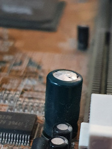
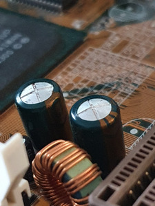
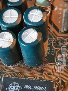
It was immediately obvious most if not all of these bigger green caps were bulging:

WhatsApp Image 2022-05-31 at 4.20.52 PM(2).jpeg
Filename
WhatsApp Image 2022-05-31 at 4.20.52 PM(2).jpeg
File size
199.55 KiB
Views
1001 views
File license
CC-BY-4.0
WhatsApp Image 2022-05-31 at 4.20.52 PM(3).jpeg
Filename
WhatsApp Image 2022-05-31 at 4.20.52 PM(3).jpeg
File size
233.81 KiB
Views
1001 views
File license
CC-BY-4.0

A couple of them have started leaking from the bottom near the CPU socket I believe?

WhatsApp Image 2022-05-31 at 4.20.52 PM(4).jpeg
Filename
WhatsApp Image 2022-05-31 at 4.20.52 PM(4).jpeg
File size
291.14 KiB
Views
1001 views
File license
CC-BY-4.0
WhatsApp Image 2022-05-31 at 4.20.52 PM(1).jpeg
Filename
WhatsApp Image 2022-05-31 at 4.20.52 PM(1).jpeg
File size
328.9 KiB
Views
1001 views
File license
CC-BY-4.0

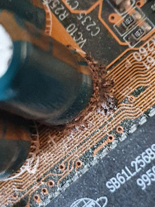
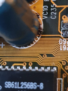
After a quick IPA cleaning, looks like there's no damage to the traces or board. I still haven't removed it all, but that remaining gunk looks exactly like what I already successfully removed, so I guess it's fine.

I have the necessary tools, and got myself a little bit of soldering skills now, so I feel pretty safe trying to fix this. But I have a few questions:

- Is it really possible that the board was still recently "tested & working" - I would definitely not feel safe trying it now with capacitors that started leaking?
- Here's what I think I'll do: take a picture of the whole board and make an numeric ID of every single green cap and its placement, de-solder them all, make a table of ID-rating, and order replacements. Any other "best practices" or general tips?
- There are medium-sized, and small-sized black caps that all look fine and flat to me, only the big green ones are bulging. What would you do - replace them anyway, or just leave them on?
- What should I look for for high-quality, long-lasting caps to replace them? Brand, type, material, whatever - this is all new to me 😀
- As for the soldering of the new caps itself, any specific tips? This doesn't look too hard of a job (famous last words 😁) with the go-through legs, I guess there's a polarity identification to make sure I put them the right way, anything else?

Thanks!

Attachments

Reply 1 of 11, by Meatball

User metadata
Rank Oldbie
Rank
Oldbie

It's possible for this board to be testing and working with the capacitors in their current condition. I've seen worse and the board still worked. I'm no electrician, but I have tested boards in need of recap, and they worked fine. I just make sure to connect them to as clean as power as possible. I have a line conditioned UPS I connect power and validate the board is working before I start on the repairs.

I only remove capacitors with the same rating at a time. This way I avoid accidently replacing a capacitor with the wrong ratings. Once the 1600s are repaired, for example, then I'll move on to 1300s and so on.

I replace all capacitors of a group. So, if even 1 1600, for example, is bulging or leaking, then I replace them all. If none of the 1300s are leaking, I leave them be. Some people like to address the entire board at once, though.

I have 2 motherboards myself I need to recap, but I don't relish the idea of spending the time to address it. Though this is an easy job, it's tedious and time consuming. Getting the polarity right is the easy part - just stay focused to avoid an accident. I occasionally mark the rear of the board with a plus (+) where the exchange is being made to remind myself to make sure the capacitor is properly installed before finishing up the solder.

I use Rubycon capacitors. You can look at the microfarad rating and voltage on the capacitors being replaced and get the same rating.

Last edited by Meatball on 2022-05-31, 15:12. Edited 5 times in total.

Reply 2 of 11, by majestyk

User metadata
Rank Oldbie
Rank
Oldbie

If you run a short test to see if the basic functions are o.k. you can do it in the current state.
Bus if you intend to use this board, run it for hours, install an OS etc, the recapping is inevitable!
Otherwise you expose important components like VRMs, chipset, CPU and memory under massive stress - thermally and electrically. This at lest shortens their lifespan or can do serious damage.
Any installed OS will not be stable.
All these crappy capacitors have lost most of their capacity. Such an electrolytic with nominal 1000µF has maybe 20µF - or less - left.
For replacement you could use Rubycon ZLS, ZLH or ZL.
You won´t regret it and it´s done in half an hour.

Reply 3 of 11, by konc

User metadata
Rank l33t
Rank
l33t
Boohyaka wrote on 2022-05-31, 14:41:

- As for the soldering of the new caps itself, any specific tips? This doesn't look too hard of a job (famous last words 😁) with the go-through legs, I guess there's a polarity identification to make sure I put them the right way, anything else?

Before soldering the new caps, desoldering the old ones might be more of a trouble.
Make sure you don't burn the board/pads hitting it with the soldering iron for too long and, I can't stress this enough, add new (preferably leaded) solder every time you need to redo a leg.

Reply 4 of 11, by Boohyaka

User metadata
Rank Oldbie
Rank
Oldbie

OK thank you for the advice so far. I will just get to it, it's a good skill to have in that hobby and I'll have to start somewhere 😀 I mean, I bought it already, I won't throw it away!
I guess I'll quickly try to turn it on up to BIOS then just to validate basic function, before getting to the recap.

Meatball wrote on 2022-05-31, 14:51:

I only remove capacitors with the same rating at a time. This way I avoid accidently replacing a capacitor with the wrong ratings. Once the 1600s are repaired, for example, then I'll move on to 1300s and so on.
I replace all capacitors of a group. So, if even 1 1600, for example, is bulging or leaking, then I replace them all. If none of the 1300s are leaking, I leave them be. Some people like to address the entire board at once, though.

My issue is that those green/gold caps are damn hard to read 🤣, if I remove them first it would be easier. Why I had this idea just to ID them A-B-C etc.. with a permanent marker, then take a picture. Then I can remove them all and check their individual rating.

Thank you @majestyk, yeah I really want to use that board and no way I expect it to work for extended time like this. I will definitely recap. And that's two mentions of Rubycon, guess that's going to be it (it sounds familiar anyway)

konc wrote on 2022-05-31, 15:09:

Before soldering the new caps, desoldering the old ones might be more of a trouble.
Make sure you don't burn the board/pads hitting it with the soldering iron for too long and, I can't stress this enough, add new (preferably leaded) solder every time you need to redo a leg.

Good advice, and a mistake I've done in the past when getting into soldering. Killed/removed a few pads like this. I've improved since then. I also got a proper desoldering gun that should be just fine for such a job, hopefully!

Reply 6 of 11, by Meatball

User metadata
Rank Oldbie
Rank
Oldbie
Boohyaka wrote on 2022-05-31, 15:33:
OK thank you for the advice so far. I will just get to it, it's a good skill to have in that hobby and I'll have to start somewh […]
Show full quote

OK thank you for the advice so far. I will just get to it, it's a good skill to have in that hobby and I'll have to start somewhere 😀 I mean, I bought it already, I won't throw it away!
I guess I'll quickly try to turn it on up to BIOS then just to validate basic function, before getting to the recap.

Meatball wrote on 2022-05-31, 14:51:

I only remove capacitors with the same rating at a time. This way I avoid accidently replacing a capacitor with the wrong ratings. Once the 1600s are repaired, for example, then I'll move on to 1300s and so on.
I replace all capacitors of a group. So, if even 1 1600, for example, is bulging or leaking, then I replace them all. If none of the 1300s are leaking, I leave them be. Some people like to address the entire board at once, though.

My issue is that those green/gold caps are damn hard to read 🤣, if I remove them first it would be easier. Why I had this idea just to ID them A-B-C etc.. with a permanent marker, then take a picture. Then I can remove them all and check their individual rating.

Thank you @majestyk, yeah I really want to use that board and no way I expect it to work for extended time like this. I will definitely recap. And that's two mentions of Rubycon, guess that's going to be it (it sounds familiar anyway)

konc wrote on 2022-05-31, 15:09:

Before soldering the new caps, desoldering the old ones might be more of a trouble.
Make sure you don't burn the board/pads hitting it with the soldering iron for too long and, I can't stress this enough, add new (preferably leaded) solder every time you need to redo a leg.

Good advice, and a mistake I've done in the past when getting into soldering. Killed/removed a few pads like this. I've improved since then. I also got a proper desoldering gun that should be just fine for such a job, hopefully!

You should have a handheld lighted magnifying glass among your tools; makes reading much easier. I have boards with the same time of capacitor, and this tool pays for itself many times over.

You have a 3rd hand station, right? Mine shown below also has a mounted/lighted magnifying glass. I can't imagine doing a solder without this equipment, now.

https://smile.amazon.com/gp/product/B077PN7FJK?psc=1

Reply 7 of 11, by rootinit

User metadata
Rank Newbie
Rank
Newbie

Just replaced some of those same-colored ones on my late '90s board. If they are the same, they would be some weird "Chhsi" brand. I used my cell phone with torch light on and a macro photo setting to reach into awkward spaces in order to read the numbers on them.

IBM ThinkPad 755Cs (Win 3.11) • IBM ThinkPad 365x (Win 98SE) • IBM ThinkPad TransNote (Win 2k)
IBM PC (PC DOS 3.30) • IBM PS/2 Model 80 (Win 3.11) • IBM PC 300GL (Win 98SE)
AT&T PC 6300 (MS-DOS 6.22) • Dell XPS T550 (Win 98SE)

Reply 8 of 11, by bstar

User metadata
Rank Newbie
Rank
Newbie

I don't know how you plan to desolder the caps, but I would not do it without a desolder iron:
https://www.amazon.com/YIHUA-Electric-Desolde … aps%2C90&sr=8-8

That one is cheap and works well. It will also take a fraction of the time to complete the job.

Reply 10 of 11, by majestyk

User metadata
Rank Oldbie
Rank
Oldbie

These desoldering stations are perfect for older mainboards. For later designs with large copper-layers in between i often found that the heat of these ststions isn´t sufficient since the small tip with a hole inside cannot transport the heat fast enough. In this case I put a second standard soldering iron (about 50-80W) directly at the tip of the desoldering gun while desoldering . You could use a third hand here. 😉

Reply 11 of 11, by PcBytes

User metadata
Rank Oldbie
Rank
Oldbie

I would do a quick power to POST screen test to see if it boots.

Afterwards, replace ALL caps from 470uF and higher.

"Enter at your own peril, past the bolted door..."
Main PC: i5 3470, GB B75M-D3H, 16GB RAM, 2x1TB
98SE : P3 650, Soyo SY-6BA+IV, 384MB RAM, 80GB