VOGONS


Debug an 8086 that won't power up

Topic actions

First post, by sndtst

User metadata
Rank Newbie
Rank
Newbie

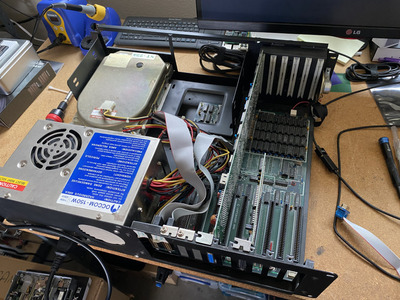
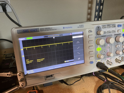
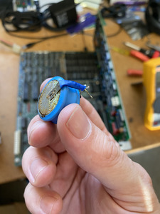
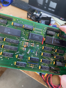
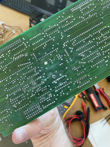
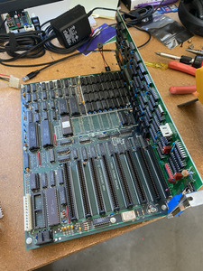
I recently got an old 8086 computer that I'm trying to bring back to life. It had a floppy controller card with a leaky battery that unfortunately spilled onto the motherboard. Before powering it on I removed all the sockets that had any appearance of corrosion, tested all of the DRAM in a Retro Chip Tester Pro (only two chips failed), and replaced the sockets with new ones and populated them with working ram. Now I'm trying to power it on for the first time and when I flip the switch on the original power supply I get nothing. The power supply fan won't start spinning. If I disconnect the power supply from the motherboard then the power supply fan starts. I tried another newer power supply and it has the same effect. I assume this is pointing to some short in the motherboard but what can I test to be sure?

Attachments

A Sound Test for as many games as I can find at SNDTST.com

Reply 1 of 22, by jakethompson1

User metadata
Rank Oldbie
Rank
Oldbie

Check out minuszerodegrees e.g. http://minuszerodegrees.net/vcf_motherboard_f … ure_history.htm - tons of good info. It's probably a tantalum capacitor. You can use a multimeter on the power connector to figure out whether it's +12V +5V -5V -12V that has the short.

Reply 2 of 22, by Horun

User metadata
Rank l33t++
Rank
l33t++

Did you try to boot without the floppy card install ?
I have a XT floppy I/O card with clock similar to what you have. It uses a special util to set/write the date and time to it, an is not Y2K compliant 😀

Hate posting a reply and then have to edit it because it made no sense 😁 First computer was an IBM 3270 workstation with CGA monitor. Stuff: https://archive.org/details/@horun

Reply 3 of 22, by sndtst

User metadata
Rank Newbie
Rank
Newbie

In continuity mode I'm getting a short beep between ground and +5 and a solid beep between ground and +12. Nothing on -5 or -12. Days also found a suspicious tantalum that appears darker than the rest. As for trying it without the card, so far I've tried it with a CGA card only and with no cards at all.

A Sound Test for as many games as I can find at SNDTST.com

Reply 4 of 22, by Horun

User metadata
Rank l33t++
Rank
l33t++

Try it with CPU and cards removed and the DVM in Ohms mode. if 0 to 3 ohms is a short, if less than 50 ohms is suspect. Most of my XT, 286, etc boards ever tested had about 100 ohm or better from any PSU connector when no cpu or cards installed.
Just a suggestion...added: and a generic answer. Depends on the board.

Hate posting a reply and then have to edit it because it made no sense 😁 First computer was an IBM 3270 workstation with CGA monitor. Stuff: https://archive.org/details/@horun

Reply 5 of 22, by ThinkpadIL

User metadata
Rank Oldbie
Rank
Oldbie

Just a note - some older PSUs need to have a certain minimum level of load in order to start. That's why on some systems special resistors were installed.

Even if it's not the main reason of your problem, it's always good to keep in mind this important detail.

Reply 6 of 22, by weedeewee

User metadata
Rank l33t
Rank
l33t
sndtst wrote on 2022-09-17, 02:35:

In continuity mode I'm getting a short beep between ground and +5 and a solid beep between ground and +12. Nothing on -5 or -12. Days also found a suspicious tantalum that appears darker than the rest. As for trying it without the card, so far I've tried it with a CGA card only and with no cards at all.

if that solid beep means a continuous beep, then you have a shorted 12v rail, and that would stop your psu from powering on.

Right to repair is fundamental. You own it, you're allowed to fix it.
How To Ask Questions The Smart Way
Do not ask Why !
https://www.vogonswiki.com/index.php/Serial_port

Reply 7 of 22, by sndtst

User metadata
Rank Newbie
Rank
Newbie

I was able to isolate and replace a single shorted tantalum capacitor and now the power supply starts up! I measured all the voltage rails and they are solidly on spec. Now I'm trying to get a beep or a video signal and so far I haven't been able to get anything. Things I have tried so far:

1: tried with nothing attached
2: tried with the hard drive power attached
3: tried with a Hercules mono card
4: tried with a CGA card
5: tried with an 8-bit trident VGA card
6: tried multiple PC speakers (no beeps)
7: tried with 2 keyboards (no led light up)
8: tried with an ISA PC analyzer (though this motherboard might be before they had post codes)

What else can I try? I'm probably going to pull out a working 386 and try the cards on them to rule out any issue with the various interface cards.

Attachments

A Sound Test for as many games as I can find at SNDTST.com

Reply 8 of 22, by mkarcher

User metadata
Rank l33t
Rank
l33t
sndtst wrote on 2022-09-18, 20:38:

8: tried with an ISA PC analyzer (though this motherboard might be before they had post codes)

It's likely that the board doesn't use POST codes at port 80. But the ISA "PC analyzer" is still useful: All power LEDS should light up, as should the CLK LED. The Reset LED should light up for some time and then turn off. The other two LEDs should show at least some activity.

Reply 9 of 22, by jakethompson1

User metadata
Rank Oldbie
Rank
Oldbie
sndtst wrote on 2022-09-18, 20:38:

What else can I try? I'm probably going to pull out a working 386 and try the cards on them to rule out any issue with the various interface cards.

Suggest getting Ruud's diagnostic ROM from over at VCFed. It will generate POST codes, but also be aware that the modern (eBay) port 80h post card doesn't work right in XT systems for reasons described over at VCFed and that I don't quite understand. You can also get codes off of the parallel port. I've considered adding serial capability to the diag rom but haven't done it so far.

Also if you have an oscilloscope or logic probe you can start sanity checking pins for the kinds of activity they should have. For example, I just repaired a board where one of the 74 logic chips had a short such that the transceiver connecting the data bus and "external" data bus (confusingly, which means not the slots but the 82xx peripheral chips onboard) was being told to constantly drive outputs on the data bus, in conflict with the CPU when it tried to do output. Someone more proficient with hardware would have found it faster than I did.

Reply 10 of 22, by weedeewee

User metadata
Rank l33t
Rank
l33t
sndtst wrote on 2022-09-18, 20:38:

I was able to isolate and replace a single shorted tantalum capacitor and now the power supply starts up! I measured all the voltage rails and they are solidly on spec.

one step further !
Any chance you can dump & upload the bios ?

Right to repair is fundamental. You own it, you're allowed to fix it.
How To Ask Questions The Smart Way
Do not ask Why !
https://www.vogonswiki.com/index.php/Serial_port

Reply 11 of 22, by sndtst

User metadata
Rank Newbie
Rank
Newbie

Well it looks like it's time to break out the oscilloscope 😀 ok so far the clock signal looks good. Also the PC tester is reporting a brief reset light and a steady ready light. I'm trying to follow along with an Adrian's Digital Basement video about what else to measure. Anyone have a recommendation for a reasonably priced EPROM programmer so I can dump this BIOS and burn a diagnostic bios?

Attachments

A Sound Test for as many games as I can find at SNDTST.com

Reply 12 of 22, by sndtst

User metadata
Rank Newbie
Rank
Newbie

Also there seems to be activity on the data bus too. I measured activity on AD0 through A14 and the data bus pins on all of the DRAM chips.

Attachments

A Sound Test for as many games as I can find at SNDTST.com

Reply 14 of 22, by vstrakh

User metadata
Rank Member
Rank
Member
sndtst wrote on 2022-09-21, 00:41:

Also there seems to be activity on the data bus too.

Looks very much like a bus contention to me. Those "steps" of intermediate level, short spikes/glitches.
Something gets to drive the bus when it's not supposed to, some buffer IC is likely misbehaving, or its control pins are being driven by damaged logic.

Reply 15 of 22, by sndtst

User metadata
Rank Newbie
Rank
Newbie

Measured the OUT1 pin (pin 13) on the 8253 and I don't see any activity (it goes high as soon as I power on the computer but never changes) I also measured the CS pin (pin 6) on the 8255 and it appears to be a regular interval but I don't know what kind of signal I should be expecting.

Attachments

A Sound Test for as many games as I can find at SNDTST.com

Reply 16 of 22, by kdr

User metadata
Rank Member
Rank
Member
sndtst wrote on 2022-09-18, 20:38:

What else can I try?

If you ground the IOCHRDY signal (pin A10) on the ISA bus and then power on the machine, the CPU will halt immediately before fetching the first instruction from ROM. This should leave all the data and address lines static and you can then check the various chip selects and bus buffers to see if there are any issues. (The CPU will be presenting the address FFFF0h on A19:A0 and the boot ROM should be selected and presenting the data 0EAh - a far JMP opcode - on D7:D0.)

Reply 17 of 22, by vstrakh

User metadata
Rank Member
Rank
Member

There are clear signs of bus contention visible on the oscilloscope waveforms.
At some moment you'll have to start pulling out the chips to find the one which messes with the bus.
In best case it would be some dead/damaged 74ls244/245, or some generic 74lsXX that produces control signals for them, or maybe simply corroded trace that does not deliver correct control signal.
But this also could be the RAM chips, or other onboard peripherals.

Reply 18 of 22, by kdr

User metadata
Rank Member
Rank
Member
vstrakh wrote on 2022-09-22, 08:58:

There are clear signs of bus contention visible on the oscilloscope waveforms.

Not necessarily. While CMOS drives 5V for a logic '1', the 74xx series TTL has weak logic '1' levels and can only get the output up to 3.6V-3.8V or so.

I can see a lot of 74LS logic on that XT clone's motherboard and the ISA card probably uses 74LS245 bus transceivers, but it's entirely possible that there is also some CMOS logic (74HCT for example) on the board. So what we're seeing on the scope might just be a CMOS device being selected and driving a 5V logic '1' followed by a 74LS device being selected and driving a 3.8V logic '1'.

Reply 19 of 22, by mogwaay

User metadata
Rank Newbie
Rank
Newbie
sndtst wrote on 2022-09-21, 00:19:

Well it looks like it's time to break out the oscilloscope 😀 ok so far the clock signal looks good. Also the PC tester is reporting a brief reset light and a steady ready light. I'm trying to follow along with an Adrian's Digital Basement video about what else to measure. Anyone have a recommendation for a reasonably priced EPROM programmer so I can dump this BIOS and burn a diagnostic bios?

You can't go wrong with Adrian's tips (or the "patron saint of old PCs" as Ctrl-Alt-Rees called him in his latest video 😀 ). As for an EPROM programmer, the TL866ii Pro from Xgecu is great and has a good range of devices - I got mine from AliExpress for about £40ish.

I think you're looking at the right things, do think a diag ROM would be helpful here as a lot of what you've checked already looks pretty good... GOOD LUCK - hopefully you'll be at the "It Freakin' Works" stage soon 😉