VOGONS


PGA132 rotator boards

Topic actions

Reply 20 of 116, by feipoa

User metadata
Rank l33t++
Rank
l33t++

Why is this much more involved than the SXL2 interposer? Seems like the worst case would have you increasing the PCB footprint, up to, but not larger than, the SXL2 interposer.

Plan your life wisely, you'll be dead before you know it.

Reply 21 of 116, by Sphere478

User metadata
Rank l33t++
Rank
l33t++

On the other interposer only Like half of them had to go across the board. on this one all of them

My fear is that there’s going to be so many traces and vias that I won’t be able to do floods which is going to make it even harder

Another thing is that on the last interposer we were able to take them across the board using only one or two layers and none or one via for most this design I fear I will have to use all six and as many vias (which protrude to all layers) for every single trace

I am not going to say that it is impossible yet but damn

I think I might actually have to use blind vias here for the routing and smd pads for the sockets. It is the only way this is making sense in my head

Last edited by Sphere478 on 2022-11-07, 02:58. Edited 2 times in total.

Sphere's PCB projects.
-
Sphere’s socket 5/7 cpu collection.
-
SUCCESSFUL K6-2+ to K6-3+ Full Cache Enable Mod
-
Tyan S1564S to S1564D single to dual processor conversion (also s1563 and s1562)

Reply 22 of 116, by feipoa

User metadata
Rank l33t++
Rank
l33t++

Maybe a 2-PCB approach is better for this application. Blind vias would demand use of PCBWay and the prices observed for PCBWay was prohibitive.

Plan your life wisely, you'll be dead before you know it.

Reply 23 of 116, by Sphere478

User metadata
Rank l33t++
Rank
l33t++
feipoa wrote on 2022-11-06, 17:54:

Maybe a 2-PCB approach is better for this application. Blind vias would demand use of PCBWay and the prices observed for PCBWay was prohibitive.

Try the bodge wire in epoxy idea. (Basically like that table I showed)

I’ll play with the pcb idea when I get in front of a computer.

Sphere's PCB projects.
-
Sphere’s socket 5/7 cpu collection.
-
SUCCESSFUL K6-2+ to K6-3+ Full Cache Enable Mod
-
Tyan S1564S to S1564D single to dual processor conversion (also s1563 and s1562)

Reply 24 of 116, by feipoa

User metadata
Rank l33t++
Rank
l33t++

There would be very little benefit from trying a bodge, or wirewrap approach. I would need to use a side-by-side protoboard. This was tried previously on a 386 class CPU and was a failure above a 16 MHz FSB. Recall,

SXL2_PGA132_wirewrap.jpg
Filename
SXL2_PGA132_wirewrap.jpg
File size
450.05 KiB
Views
714 views
File license
CC-BY-4.0

Plan your life wisely, you'll be dead before you know it.

Reply 25 of 116, by elbbar

User metadata
Rank Newbie
Rank
Newbie

I thought this was an interesting idea, so I plugged it into eagle to see what it would do. If you just rotate the pins and hook each one up then it can easily route in 4 layers. It will also route in 2 layers, but the board needs to be bigger. Using surface mount parts is probably how I would do it, but I also tried a thru-hole version with the grid shifted over. I don't know how hard it would be to assemble this, but Advanced Interconnections makes a variety of parts that could probably make it possible.

I was not sure on the pin grid pitch so I used 2.54mm and used your picture above to get the 132-pin arrangement. This was just to see if it could work, so there are certainly tweaks that could be made to the design rules to put in more copper, etc. There could also be improvements by going through the specific pinouts, but another possible advantage of routing/rotating all 132 pins is that there is no "Pin 1" and with the shifted pin pattern you could also rotate the adapter to both shift and rotate the chip as desired.

PGA132wires.png
Filename
PGA132wires.png
File size
33.26 KiB
Views
697 views
File license
CC-BY-4.0
PGA132smt.png
Filename
PGA132smt.png
File size
81.68 KiB
Views
697 views
File license
CC-BY-4.0
PGA132pins.png
Filename
PGA132pins.png
File size
60.3 KiB
Views
697 views
File license
CC-BY-4.0

Reply 26 of 116, by Sphere478

User metadata
Rank l33t++
Rank
l33t++

Beautiful!

2.54 is correct I believe,

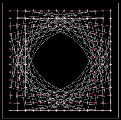
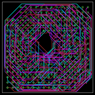
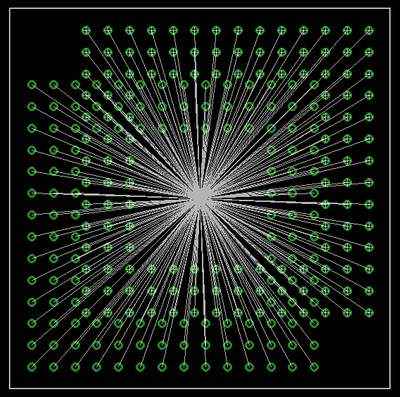
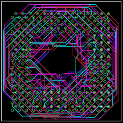
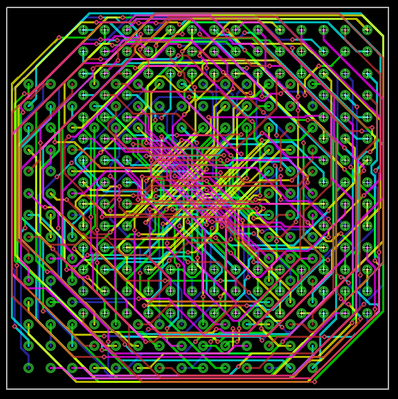
Those nets look exactly like I visualized them.

The image is kinda small on my phone, and I am unfamiliar with eagle is that all connected? Do you intend on finishing this? Do you consider this just a draft or something you can tweak to compleetion?

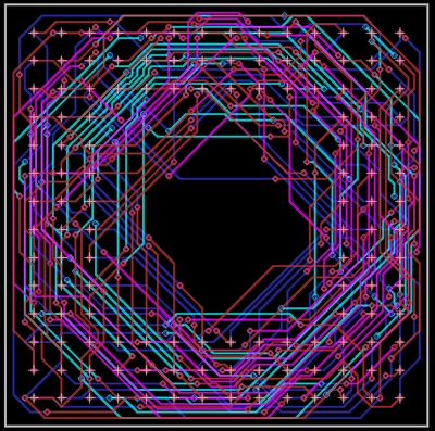
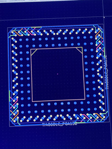
I was imagining issues with too many vias everywhere to connect to the smd pads. I had intended on routing on the internal layers as much as possible but I suppose routing on the top and bottom would save a lot of vias for smd setup. 🤔

How do your floods look? Or will you need extra layers for it?

Being that the problem is so geometric, I was hoping for a symmetric solution a pattern to the routing ya know.

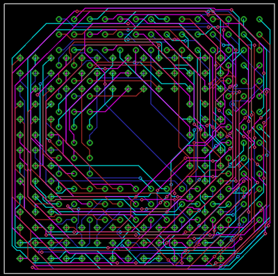
I agree that smd looks like the way to go from a pcb design standpoint

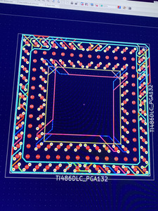
I also agree that maybe routing all of them and forgetting about power floods may be an option.

I would at the very least like to flood grond though. Perhaps there is a ground pin in a location that is equal on all 4 orientations

Sphere's PCB projects.
-
Sphere’s socket 5/7 cpu collection.
-
SUCCESSFUL K6-2+ to K6-3+ Full Cache Enable Mod
-
Tyan S1564S to S1564D single to dual processor conversion (also s1563 and s1562)

Reply 28 of 116, by elbbar

User metadata
Rank Newbie
Rank
Newbie

There may be an elegant symmetric routing for the surface mount version, but the shifted pin array version breaks it. One other advantage of the pin version is that the rotate left is the same board as the rotate right--just install the pins on the other side of the board.

I'm mostly just tinkering. I don't know the level of interest here, and the details depend on how it can be made. How much of a shift is actually needed for assembly? These guys might have some good ideas for actually making these adapters:

https://www.advanced.com/products/ic-socket-a … dapters/options

Sure a 12-layer board would be nice, but you can get 4-layer in small batches from places like oshpark. If that big stack of pin sockets will work, then a little rat's nest of traces might also. Here is a version that has wider traces and should meet oshpark's 4-layer design rules. I think the pin holes are 0.6mm, so it might depend on what size pins you'd want to install. Bigger holes take up room for wires...

PGA132pinsB.png
Filename
PGA132pinsB.png
File size
81.39 KiB
Views
659 views
File license
CC-BY-4.0

Reply 29 of 116, by Sphere478

User metadata
Rank l33t++
Rank
l33t++

What happens if you only offset it 1.27 x 1.27y

This was my planned approach for a thru hole setup. Is it possible?

Yeah, my brain won’t be happy until I see something symetrical hahah 😂

Very nice work of course though. 😀

I’d be tinkering with it also but I’m on my phone away from computer still.

Sphere's PCB projects.
-
Sphere’s socket 5/7 cpu collection.
-
SUCCESSFUL K6-2+ to K6-3+ Full Cache Enable Mod
-
Tyan S1564S to S1564D single to dual processor conversion (also s1563 and s1562)

Reply 30 of 116, by feipoa

User metadata
Rank l33t++
Rank
l33t++

Are we sure the ground plane isn't necessary? The path lengths for the rotator board will have, perhaps, half the length of those from the unshielded prototype shown above and it was choking at low frequencies. There are, combined, 41 ground and Vcc pins. Wouldn't having Vcc and GND planes greatly reduce the quantity of traces needed? A 6-layer wouldn't be a show stopper, but 4 would be a lot more ideal. The through-hole approach is preferred so that anyone with the gerbers can assemble it with minimal soldering skills. On the other hand, elbbar is there a particular product you are recommending from Advance Interconnects which will allow simple assembly of 132 PGA pins via surface mount?

Plan your life wisely, you'll be dead before you know it.

Reply 31 of 116, by elbbar

User metadata
Rank Newbie
Rank
Newbie

I shifted the pin version that way because it exposes most of the pins while keeping the board small. How would you build it if all the pins are covered? I don't know how I would do it, but it seems like there must be something to make it easier if surface mount is not desirable. I did see the solder preform idea. This would be similar to surface mount. Again, the details depend on how you plan to make it.

solderPreform.png
Filename
solderPreform.png
File size
91.74 KiB
Views
607 views
File license
CC-BY-4.0

On the hand-made adapter, have you tried adding some bypass caps on the CPU socket? The power/ground pins are usually next to each other so you might be able to add little ceramic caps directly across pins on the CPU.

I think the 180 version would need more layers. This is a sort of worst case:

PGA132pins180.png
Filename
PGA132pins180.png
File size
41.13 KiB
Views
607 views
File license
CC-BY-4.0

Reply 32 of 116, by Sphere478

User metadata
Rank l33t++
Rank
l33t++

^at that pic, 😵💫

Check out Feiopa’s other thread

Custom interposer module for TI486SXL2-66 PGA168 to PGA132 - HELP!

He figured out a way to assemble them.

feipoa wrote on 2022-11-08, 11:09:

Are we sure the ground plane isn't necessary? The path lengths for the rotator board will have, perhaps, half the length of those from the unshielded prototype shown above and it was choking at low frequencies. There are, combined, 41 ground and Vcc pins. Wouldn't having Vcc and GND planes greatly reduce the quantity of traces needed? A 6-layer wouldn't be a show stopper, but 4 would be a lot more ideal. The through-hole approach is preferred so that anyone with the gerbers can assemble it with minimal soldering skills. On the other hand, elbbar is there a particular product you are recommending from Advance Interconnects which will allow simple assembly of 132 PGA pins via surface mount?

Personally, I also would like to see a ground plane.

Sphere's PCB projects.
-
Sphere’s socket 5/7 cpu collection.
-
SUCCESSFUL K6-2+ to K6-3+ Full Cache Enable Mod
-
Tyan S1564S to S1564D single to dual processor conversion (also s1563 and s1562)

Reply 33 of 116, by elbbar

User metadata
Rank Newbie
Rank
Newbie

The 90 degree version can still route in 4 layers with a half-pin shift. If you wanted a ground plane you could make it as a 6 layer. Are the power and ground pins symmetric? Since you can plug the CPU in 4 different ways, it would be nice if it wouldn't fry when plugged in wrong.

PGA132pinsC.png
Filename
PGA132pinsC.png
File size
72.03 KiB
Views
584 views
File license
CC-BY-4.0

The 180 degree version can route in 6 layers.

PGA132pins180B.png
Filename
PGA132pins180B.png
File size
145.24 KiB
Views
584 views
File license
CC-BY-4.0

Reply 34 of 116, by H3nrik V!

User metadata
Rank Oldbie
Rank
Oldbie

Wonder if 180 degrees would be better achieved by stacking 2 90 degrees interposers?

Please use the "quote" option if asking questions to what I write - it will really up the chances of me noticing 😀

Reply 35 of 116, by Sphere478

User metadata
Rank l33t++
Rank
l33t++

Here is the result of some tinkering I did.

So far so good. But more pins routed will tell the real tale of how doomed this attempt may be 🤣.

Attachments

  • image.jpg
    Filename
    image.jpg
    File size
    1.69 MiB
    Views
    516 views
    File license
    Public domain

Sphere's PCB projects.
-
Sphere’s socket 5/7 cpu collection.
-
SUCCESSFUL K6-2+ to K6-3+ Full Cache Enable Mod
-
Tyan S1564S to S1564D single to dual processor conversion (also s1563 and s1562)

Reply 36 of 116, by Sphere478

User metadata
Rank l33t++
Rank
l33t++

And more tinkering

Attachments

  • image.jpg
    Filename
    image.jpg
    File size
    1.54 MiB
    Views
    507 views
    File license
    Public domain

Sphere's PCB projects.
-
Sphere’s socket 5/7 cpu collection.
-
SUCCESSFUL K6-2+ to K6-3+ Full Cache Enable Mod
-
Tyan S1564S to S1564D single to dual processor conversion (also s1563 and s1562)

Reply 37 of 116, by Sphere478

User metadata
Rank l33t++
Rank
l33t++

Spent a while playing with this again. I swear there is a geometric way to set this up. there has to be a way other than spaghetti.

Sphere's PCB projects.
-
Sphere’s socket 5/7 cpu collection.
-
SUCCESSFUL K6-2+ to K6-3+ Full Cache Enable Mod
-
Tyan S1564S to S1564D single to dual processor conversion (also s1563 and s1562)

Reply 38 of 116, by feipoa

User metadata
Rank l33t++
Rank
l33t++

Are both sides surface mount? I'm OK to give that a go using solder paste. Double surface mount means 2-layer or 4-layer?

Plan your life wisely, you'll be dead before you know it.

Reply 39 of 116, by Sphere478

User metadata
Rank l33t++
Rank
l33t++

I’m routing in 6 layer for my attenpt.

Yes, two surface mount.

Unfortunately this means every pad will have two vias beside it. I can cover them with silk though.

Sphere's PCB projects.
-
Sphere’s socket 5/7 cpu collection.
-
SUCCESSFUL K6-2+ to K6-3+ Full Cache Enable Mod
-
Tyan S1564S to S1564D single to dual processor conversion (also s1563 and s1562)