These are for filtering the 5V USB supply voltage (EMV), they must stand the full current caused by the connected USB devices.
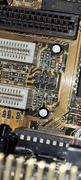
On early USB mainboards they used through hole "ferrite beads" with very low inductivity, very low DC-resistance (0.05 Ohm) and designed for currents of 1-2A.
There are also SMD ferrite beads for example the Murata "BLM21SP471SN1D" (form factor 805).
You can use anything like that, the impedance is not critical (about 500 ohm @ 100 MHz).
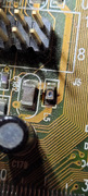
According to most application notes there was also a fuse in every supply line. This does not seem to be the case here. Maybe the original inductor is made of a thinner wire that melts in case of a short. Mainboard makers are very inventive when they can save a few cents.
If you choose a standard inductor instaed of a ferrite bead, just make sure the wire is thick enough to stand 1-2A.