VOGONS


First post, by mrfusion92

User metadata
Rank Member
Rank
Member

I knew that this post would have been necessary.

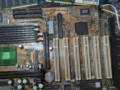
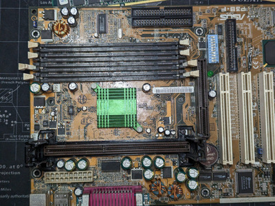
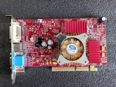
So I bought an Asus P2B and a P3B-F. Sold as unkown working status. They arrived yesterday.

And... of course they don't work.

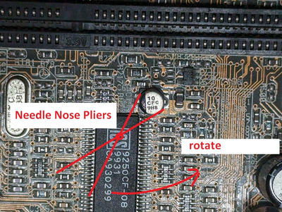
The P2B was easy to diagnostic. The MOSFET in Q10 is missing on the top. Yeah I didn't notice in the seller photos.
Does anyone know the exact component?

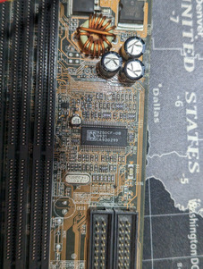
The P3B-F is whole another story. It doesn't do anything with the CPU plugged in, not even a beep.

PXL_20230602_142034915.MP.jpg
Filename
PXL_20230602_142034915.MP.jpg
File size
1.72 MiB
Views
1374 views
File license
Fair use/fair dealing exception

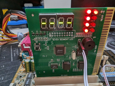
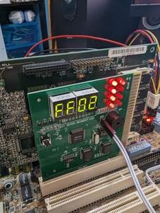
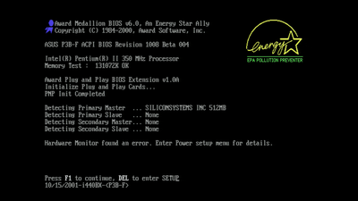
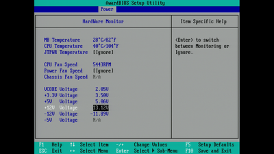
With the CPU removed the speaker does a reapeating pattern of LOW and HIGH beeps, which means and I quote "Either the CPU is not seated properly or the CPU is damaged. May also be due to excess heat. Check the CPU fan or BIOS settings for proper fan speed."

What I have tried so far:

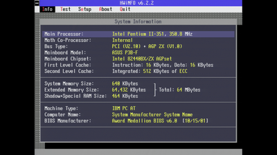
  • two PII 350Mhz CPUs. Tested also JumperFree mode.
  • different RAM modules or none at all.
  • two know good PSUs.
  • flashed different BIOS versions. Now there is this one.
  • new CMOS battery.
  • cleaned CPU slot edge connector.

Another maybe interesting detail, I tried still with a video card and my KVM switch doesn't turn on at all. That KVM even without a proper video signal it turns on when it is plugged to a powered on video card.

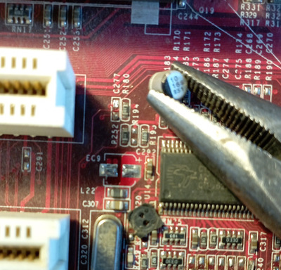
I don't see any physical damage but I know that caps can go bad without any visible defect. Before going down the road of recapping the full thing, is there something else that I can check?
I know that they are really good motherboards (when they work) so I really want to try to get them fixed.

PXL_20230602_142229359.jpg
Filename
PXL_20230602_142229359.jpg
File size
1.98 MiB
Views
1374 views
File license
Fair use/fair dealing exception
PXL_20230602_142224928.jpg
Filename
PXL_20230602_142224928.jpg
File size
2 MiB
Views
1374 views
File license
Fair use/fair dealing exception

Reply 1 of 38, by Zerthimon

User metadata
Rank Member
Rank
Member

Try this: set the jen jumper to a jumperfree mode, then connect only the CPU, power it on, then after one minute check if anything is getting hot on the board (both bridges, Asus (monitoring) chip, winbond (sio) chip) etc.

Reply 2 of 38, by mrfusion92

User metadata
Rank Member
Rank
Member

I am speechless...

I was doing what @Zerthimon said, while touching around all the chips... the motherboard started POSTing under my eyes.

Powered off, plugged RAM and video card.... and I was able to go to the BIOS and even boot my bench DOS CF card.

PXL_20230602_152708156.jpg
Filename
PXL_20230602_152708156.jpg
File size
1.21 MiB
Views
1349 views
File license
Fair use/fair dealing exception
Screenshot 2023-06-02 17-26-54.png
Filename
Screenshot 2023-06-02 17-26-54.png
File size
1.17 MiB
Views
1349 views
File license
Fair use/fair dealing exception

I think it started POSTing after I touched\pushed this chip, which I think is the clock generator. It also gets hot, is it normal?
No other chips got too hot, only that.

PXL_20230602_151726652.jpg
Filename
PXL_20230602_151726652.jpg
File size
1.35 MiB
Views
1349 views
File license
Fair use/fair dealing exception

Reply 5 of 38, by mrfusion92

User metadata
Rank Member
Rank
Member

And indeed after a couple of hours while I left the motherboard disconnected I'm back to square one with zero signs of post.

The clock chip gets very hot, I can't leave my finger on it more than 3 seconds. This also while it was working.

I'm not so good with the desoldering. Like I did a small recap in a Pentium 4 motherboard, it works now but desoldering the caps was a nightmare for me.

Reply 7 of 38, by mrfusion92

User metadata
Rank Member
Rank
Member

Basically now it's a diesel engine, it needs 5/10 minutes to warm up then it boots 🤣

But I've noticed this now, it gives me this hardware error which I've ignored so far thinking it was because of the missing floppy disk drive .

Screenshot 2023-06-03 09-22-47.png
Filename
Screenshot 2023-06-03 09-22-47.png
File size
450.76 KiB
Views
1226 views
File license
Fair use/fair dealing exception

And the error is about the 12v rail. I disabled the monitoring of it and the error got away. Tested two PSUs and reading was about the same. The voltage read out got from a molex with a multimeter is in spec.
How can I know which caps are on the 12v rail?

Screenshot 2023-06-03 09-19-34.png
Filename
Screenshot 2023-06-03 09-19-34.png
File size
1.24 MiB
Views
1226 views
File license
Fair use/fair dealing exception
verysaving wrote on 2023-06-03, 00:41:

Try replacing the tiny smd cap near the clock generator.
Bigger caps seem to be Rubycon and Sanyo and they age
usually well if not thermal stressed.

Oh god that tiny little cap? If I try to remove it I will end up ruining this motherboard even more. Besides I can't understand the values of it.

PXL_20230603_070028873.jpg
Filename
PXL_20230603_070028873.jpg
File size
1.66 MiB
Views
1226 views
File license
Fair use/fair dealing exception

Reply 8 of 38, by Horun

User metadata
Rank l33t++
Rank
l33t++

Appears to be a Panasonic Alumimum cap. 10uF 16v SMT. The 10 is for 10uf, CFC is voltage/series. first letter is voltage, C for 16v, FC is the series. Bottom stuff is the lot.
From this pdf: https://www.farnell.com/datasheets/2813661.pdf and this for a 10uF 50v: https://ph.rs-online.com/web/p/aluminium-capacitors/0568777

Hate posting a reply and then have to edit it because it made no sense 😁 First computer was an IBM 3270 workstation with CGA monitor. Stuff: https://archive.org/details/@horun

Reply 9 of 38, by ediflorianUS

User metadata
Rank Member
Rank
Member

Congrats on fixing(to P.O.S.T) . I wanted to suggest setting the MB jumpers manually , because I had better luck doing everything manually.

P.S. instead of changing SMD caps (if they are not in short) try just cleaning them with electronic contact cleaner (I Use italian DUECI Electronic)

My 80486-S i66 Project

Reply 11 of 38, by shevalier

User metadata
Rank Member
Rank
Member
mrfusion92 wrote on 2023-06-03, 07:37:

If I try to remove it I will end up ruining this motherboard even more. Besides I can't understand the values of it.

#1 Never try to desolder the SMD electrolyte.
#2 Never try to solder smd electrolyte without heating from below.
Use SMD tantalum capacitors or MLСС
Hint
You should collecting non-working hardware.
For example, Radeon 9xxx, which does not work, not only look good on the shelf, but also serve as a source of SMD tantalum capacitors 10-22uF 6.3-16V.

Attachments

  • Untitled.jpg
    Filename
    Untitled.jpg
    File size
    375.77 KiB
    Views
    1126 views
    File license
    Public domain

Aopen MX3S, PIII-S Tualatin 1133, Radeon 9800Pro@XT BIOS, Diamond monster sound MX300
JetWay K8T8AS, Athlon DH-E6 3000+, Radeon HD2600Pro AGP, Audigy 2 Value

Reply 12 of 38, by mrfusion92

User metadata
Rank Member
Rank
Member
shevalier wrote on 2023-06-04, 04:06:
#1 Never try to desolder the SMD electrolyte. #2 Never try to solder smd electrolyte without heating from below. Use SMD tantalu […]
Show full quote

#1 Never try to desolder the SMD electrolyte.
#2 Never try to solder smd electrolyte without heating from below.
Use SMD tantalum capacitors or MLСС
Hint
You should collecting non-working hardware.
For example, Radeon 9xxx, which does not work, not only look good on the shelf, but also serve as a source of SMD tantalum capacitors 10-22uF 6.3-16V.

I do have a Radeon 9200 which shows artifacts with probably bad vram chips! And indeed seems to have three 10 uF caps but I think that they are rated for 16v. Is that an issue?

PXL_20230604_133652858.jpg
Filename
PXL_20230604_133652858.jpg
File size
1.45 MiB
Views
1088 views
File license
Fair use/fair dealing exception

However, the fact remains that I am not equipped for this type of work. I will probably need at least an hot air gun.

Reply 13 of 38, by shevalier

User metadata
Rank Member
Rank
Member
mrfusion92 wrote on 2023-06-04, 13:45:

And indeed seems to have three 10 uF caps but I think that they are rated for 16v. Is that an issue?

This will show only the replacement

mrfusion92 wrote on 2023-06-04, 13:45:

However, the fact remains that I am not equipped for this type of work. I will probably need at least an hot air gun.

You can't solder them with a soldering iron, see picture.
Hot air gun - overheating.

Finally use MLCC, the 21st century is ending...

Attachments

  • MLCC.jpg
    Filename
    MLCC.jpg
    File size
    170.75 KiB
    Views
    1076 views
    File license
    Public domain
  • SMD electrolitic cap.jpg
    Filename
    SMD electrolitic cap.jpg
    File size
    38.47 KiB
    Views
    1076 views
    File license
    Public domain

Aopen MX3S, PIII-S Tualatin 1133, Radeon 9800Pro@XT BIOS, Diamond monster sound MX300
JetWay K8T8AS, Athlon DH-E6 3000+, Radeon HD2600Pro AGP, Audigy 2 Value

Reply 14 of 38, by shevalier

User metadata
Rank Member
Rank
Member

Or tantalum capacitors, in a pinch

Attachments

Aopen MX3S, PIII-S Tualatin 1133, Radeon 9800Pro@XT BIOS, Diamond monster sound MX300
JetWay K8T8AS, Athlon DH-E6 3000+, Radeon HD2600Pro AGP, Audigy 2 Value

Reply 15 of 38, by bloodem

User metadata
Rank Oldbie
Rank
Oldbie
shevalier wrote on 2023-06-04, 04:06:

#1 Never try to desolder the SMD electrolyte.

Wut?

shevalier wrote on 2023-06-04, 04:06:

#2 Never try to solder smd electrolyte without heating from below.

Wut?

shevalier wrote on 2023-06-04, 15:02:

You can't solder them with a soldering iron, see picture.

Again... wut?

1 x PLCC-68 / 2 x PGA132 / 5 x Skt 3 / 9 x Skt 7 / 12 x SS7 / 1 x Skt 8 / 14 x Slot 1 / 5 x Slot A
5 x Skt 370 / 8 x Skt A / 2 x Skt 478 / 2 x Skt 754 / 3 x Skt 939 / 7 x LGA775 / 1 x LGA1155
Current PC: Ryzen 7 5800X3D
Backup PC: Core i7 7700k

Reply 16 of 38, by shevalier

User metadata
Rank Member
Rank
Member

Everyone says WUT.
But not everyone shows results.
The photo shows a complete reflow of solder at the factory, and not 1 mm of snot.

Attachments

Aopen MX3S, PIII-S Tualatin 1133, Radeon 9800Pro@XT BIOS, Diamond monster sound MX300
JetWay K8T8AS, Athlon DH-E6 3000+, Radeon HD2600Pro AGP, Audigy 2 Value

Reply 17 of 38, by Roman555

User metadata
Rank Oldbie
Rank
Oldbie
mrfusion92 wrote on 2023-06-02, 22:31:

And indeed after a couple of hours while I left the motherboard disconnected I'm back to square one with zero signs of post.

The clock chip gets very hot, I can't leave my finger on it more than 3 seconds. This also while it was working.

I'm not so good with the desoldering. Like I did a small recap in a Pentium 4 motherboard, it works now but desoldering the caps was a nightmare for me.

A good clock generator can be very hot. Usually if it isn't warm at all then it doesn't do its job. So I wouldn't pay attention to its hotness.
What about that little capacitor - try to add an usual (not smd) electrolytic capacitor in parallel to it. Just don't confuse where + and - pins. To diagnostic matter I wouldn't even solder it. I think it is easier than replace the smd cap.

[ MS6168/PII-350/YMF754/98SE ]
[ 775i65G/E5500/9800Pro/Vortex2/ME ]

Reply 18 of 38, by Doornkaat

User metadata
Rank l33t
Rank
l33t
bloodem wrote on 2023-06-04, 15:29:
Wut? […]
Show full quote
shevalier wrote on 2023-06-04, 04:06:

#1 Never try to desolder the SMD electrolyte.

Wut?

shevalier wrote on 2023-06-04, 04:06:

#2 Never try to solder smd electrolyte without heating from below.

Wut?

shevalier wrote on 2023-06-04, 15:02:

You can't solder them with a soldering iron, see picture.

Again... wut?

I'm also confused. Regularly soldered SMD electrolytics with a regular iron withput preheating the board or anything. No issues so far.🤷‍♂️
Edit: Are you by any chance not using flux or are you using an iron with too low temperature, shevalier?

Reply 19 of 38, by mrfusion92

User metadata
Rank Member
Rank
Member

Setting aside the technique to solder. I'm writing the shopping list of caps to buy, and I will replace all of them. The through hole ones and also the other SMDs.

I have cross-checked with this webpage. That part list is for the rev 1.03, mine is the 1.04 and there is only one 100 uF cap more. All the others are exactly the same.
That page doesn't mention the smd caps, which are 5 in total and are all the same like the one near the clock chip.

I'm just unsure which type of smd caps I should buy. MLCC seems to be easy to solder and I've found this, is it correct? The size too?

Otherwise I've found this that seems to be a "drop-in replacement".

Roman555 wrote on 2023-06-04, 17:30:

A good clock generator can be very hot. Usually if it isn't warm at all then it doesn't do its job. So I wouldn't pay attention to its hotness.
What about that little capacitor - try to add an usual (not smd) electrolytic capacitor in parallel to it. Just don't confuse where + and - pins. To diagnostic matter I wouldn't even solder it. I think it is easier than replace the smd cap.

I have only some ceramic 100uF caps from a small electric project I was doing. I don't think I can use them for test. Besides today it is behaving way better, it failed only the first boot. I will leave it disconnected the whole night and see if tomorrow morning it will be dead.