VOGONS

Common searches


Voltages/Arduino experts question

Topic actions

First post, by 386SX

User metadata
Rank l33t
Rank
l33t

Hi,

I'm lately testing the Arduino development board, a 16Mhz Atmel328 microcontroller based Input/Output board many will already know. I've a separate module I was testing with, that depending of the input power, it gives out a voltages that decrease from 2.15 volts to 0.10 volts depending on the configuration it was manufactured with a linear decrease when the dBm measured increase.
Considering the module itself would work even without the Arduino microcontroller but I wanted the voltages to increase instead of decrease, is there some simple circuit or external ICs to convert the voltage exactly the opposite with the highest sensibility to the voltages changes?
I was reading something about inverting summing amplifier but it would give a negative output. I just need to reverse the 2.15 to 0.10 and the 0.10 to 2.15 and every values in between.

Thanks

Reply 1 of 22, by SirNickity

User metadata
Rank Oldbie
Rank
Oldbie

An op-amp's inverting input could do that. Op-amps are typically run with dual supplies, but they don't have to be. There's a V+ and V- input. There's no requirement that they be equidistant from your circuit's common Gnd.

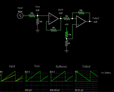
What you can do is use an op-amp with a single supply, and generate a 1/2 Vcc to use as a virtual "ground" reference. Something like this would work:

Invert.png
Filename
Invert.png
File size
32.48 KiB
Views
713 views
File license
Fair use/fair dealing exception

The first stage uses a voltage divider to cut the 0-5V signal to a 0-2.5V signal, so we have some headroom later on. Then there's a non-inverting buffer amp to remove the source impedance of that stage.

The second part uses the 10K series resistor and the 20K feedback resistor to set the gain to 2X to compensate for the 0.5X gain in the beginning. You might want to substitute that 20K for a slightly smaller resistor plus a rheostat (pot with one leg tied to the wiper) so you can trim the gain. You can also add a trimmer from the junction of the 10K and 20K to ground if you need to adjust the offset from 0V to avoid clipping. (Op-amps are not 100% rail-to-rail, so they can't output exactly V+ or V-.)

The bottom voltage divider between +5V and Gnd serves as your floating reference of 2.5V. (EDIT: Oops, sorry -- it's actually 1.66V here, or 1/3 Vcc, which is what you happen to need to center the 2.5V PtP waveform with the gain of this system.) The more stable this voltage, the better. Minimally, you might want a 100nF cap from the midpoint to Gnd. Optimally, your +5V should be from a filtered linear regulator, or replace the divider with a dedicated voltage reference. But the precision you need is up to you.

The output should be an inverse of the input.

Reply 2 of 22, by 386SX

User metadata
Rank l33t
Rank
l33t
SirNickity wrote:
An op-amp's inverting input could do that. Op-amps are typically run with dual supplies, but they don't have to be. There's a […]
Show full quote

An op-amp's inverting input could do that. Op-amps are typically run with dual supplies, but they don't have to be. There's a V+ and V- input. There's no requirement that they be equidistant from your circuit's common Gnd.

What you can do is use an op-amp with a single supply, and generate a 1/2 Vcc to use as a virtual "ground" reference. Something like this would work:

Invert.png

The first stage uses a voltage divider to cut the 0-5V signal to a 0-2.5V signal, so we have some headroom later on. Then there's a non-inverting buffer amp to remove the source impedance of that stage.

The second part uses the 10K series resistor and the 20K feedback resistor to set the gain to 2X to compensate for the 0.5X gain in the beginning. You might want to substitute that 20K for a slightly smaller resistor plus a rheostat (pot with one leg tied to the wiper) so you can trim the gain. You can also add a trimmer from the junction of the 10K and 20K to ground if you need to adjust the offset from 0V to avoid clipping. (Op-amps are not 100% rail-to-rail, so they can't output exactly V+ or V-.)

The bottom voltage divider between +5V and Gnd serves as your floating reference of 2.5V. (EDIT: Oops, sorry -- it's actually 1.66V here, or 1/3 Vcc, which is what you happen to need to center the 2.5V PtP waveform with the gain of this system.) The more stable this voltage, the better. Minimally, you might want a 100nF cap from the midpoint to Gnd. Optimally, your +5V should be from a filtered linear regulator, or replace the divider with a dedicated voltage reference. But the precision you need is up to you.

The output should be an inverse of the input.

Thanks! I'm going to study into this. Are there any cheap amp ics names to suggest buying? The idea was that the resulting output would be connected to a speaker to really "hear" different frequency disturbances like some sort of an old "AM radio". 😜
Would you think it would be possible breaking the DC current and with a 3W amplifier?

Reply 3 of 22, by SirNickity

User metadata
Rank Oldbie
Rank
Oldbie

Which op-amp... man, there are tons to choose from. I think I would hit up your favorite parts distributor and use the parametric search to find one you like. Probably most important is that it has 0-5V supply capability. It's not really the lack of negative VDC that's an issue, because 0-5V is essentially the same as -2.5V to +2.5V as far as the op-amp is concerned. But, you do need to make sure the IC is comfortable at that low voltage, and has near rail-to-rail swing. The ubiquitous TL071, for example, wants more than 5V to run stable. Typical audio op-amps are often run at something like +/-15V -- so 30V. But, thanks to the proliferation of portable applications, there is no shortage of low-voltage ICs available. If you want to thin the herd, look for 0-5V, "rail-to-rail" (it'll only be "nearly" rail to rail in reality), unity-gain stable, preferably with no need for external compensation (more external circuitry), and 2 op-amps in one package, DIP unless you're into surface-mount stuff. Then, sort by price. Bandwidth won't matter since even the slowest of garden-variety op-amps will be fine with audio-range signals.

Not sure what you mean by breaking the DC? You mean turn it into an AC audio signal? Really all you need is a capacitor to AC-couple the output of the circuit above into your audio amp, but there are other ways to deal with it as well. Kind of depends on what supply rails you have at your disposal and how complex you're willing to make the circuit. For that matter, if the DC voltage swing is slow-moving, you can feed it to a voltage-controlled oscillator to get something more suited to human hearing.

3W is actually quite a bit... Audio guys always talk about "the first watt" as being the most important, since it's a logarithmic scale. This is one of those projects that the good old LM386 is well suited for -- particularly if all you have is +VDC anyway.

Reply 4 of 22, by gdjacobs

User metadata
Rank l33t++
Rank
l33t++

If you have a case where measured power is fairly steady but you want some kind of audible cue when it changes, you could input the above circuit into a voltage controlled oscillator to have the output frequency change with power or the waveform amplitude change with power. In either case, for audio applications this is now usually performed digitally. The MCU on an Arduino Teensy would certainly be capable enough to do this at audio frequencies.

All hail the Great Capacitor Brand Finder

Reply 5 of 22, by SirNickity

User metadata
Rank Oldbie
Rank
Oldbie

Yeah, that's probably an easier way to do it than the analog circuit, actually. For example, you could read the DC input via an ADC channel, then set a PWM output duty cycle or divisor based on the ADC value.

Reply 6 of 22, by 386SX

User metadata
Rank l33t
Rank
l33t
SirNickity wrote:

Which op-amp... man, there are tons to choose from. I think I would hit up your favorite parts distributor and use the parametric search to find one you like. Probably most important is that it has 0-5V supply capability. It's not really the lack of negative VDC that's an issue, because 0-5V is essentially the same as -2.5V to +2.5V as far as the op-amp is concerned. But, you do need to make sure the IC is comfortable at that low voltage, and has near rail-to-rail swing. The ubiquitous TL071, for example, wants more than 5V to run stable. Typical audio op-amps are often run at something like +/-15V -- so 30V. But, thanks to the proliferation of portable applications, there is no shortage of low-voltage ICs available. If you want to thin the herd, look for 0-5V, "rail-to-rail" (it'll only be "nearly" rail to rail in reality), unity-gain stable, preferably with no need for external compensation (more external circuitry), and 2 op-amps in one package, DIP unless you're into surface-mount stuff. Then, sort by price. Bandwidth won't matter since even the slowest of garden-variety op-amps will be fine with audio-range signals.

Not sure what you mean by breaking the DC? You mean turn it into an AC audio signal? Really all you need is a capacitor to AC-couple the output of the circuit above into your audio amp, but there are other ways to deal with it as well. Kind of depends on what supply rails you have at your disposal and how complex you're willing to make the circuit. For that matter, if the DC voltage swing is slow-moving, you can feed it to a voltage-controlled oscillator to get something more suited to human hearing.

3W is actually quite a bit... Audio guys always talk about "the first watt" as being the most important, since it's a logarithmic scale. This is one of those projects that the good old LM386 is well suited for -- particularly if all you have is +VDC anyway.

Thanks! Yes breaking the DC current I meant that sorry 😁. I have a PAM4803 amplifier board already built with 5V input and 3Wx2 output and for the DC problem I I already put a capacitor (0.47uF) in serie but maybe wrong..at the output of the amplifier, not the input. Do I need to put it at the input of the amplifier?

Reply 7 of 22, by 386SX

User metadata
Rank l33t
Rank
l33t
gdjacobs wrote:

If you have a case where measured power is fairly steady but you want some kind of audible cue when it changes, you could input the above circuit into a voltage controlled oscillator to have the output frequency change with power or the waveform amplitude change with power. In either case, for audio applications this is now usually performed digitally. The MCU on an Arduino Teensy would certainly be capable enough to do this at audio frequencies.

For what I've seen the output voltages of the module changes with much speed like 10ns and in the Arduino code it basically gives me problem for using any "delay()" function I could need in the code. It's a very sensible input and difficult to translate in output (with all those logarithmic logics from the datasheets) and I was thinking to have the dBm showed with a series of LEDs depending on a fastest real time voltages reading of the analog input of the Arduino, but for the "audio" part I thought connecting a speaker directly to the DC voltage of the external board it will result in a more realistic "sound" beside all the electric/noises it will obviously have.
Also the Nano board (maybe it's too cheap who knows) doesn't look like a real good Analog reading tool. My multimeter read 2.10 volts when the microcontroller read 2.15 or more and that difference is too big for the voltage->dBm expression.
At first I was thinking to use a piezo "speaker" depending of the 0-1023 values reading of the 0-5v input of the Nano board. It worked but the module itself is quite wideband and this, as first arduino project idea was to "feel" different sounds with different noises and I thought staying "analog" may be is better for this.

Reply 8 of 22, by gdjacobs

User metadata
Rank l33t++
Rank
l33t++
SirNickity wrote:

Yeah, that's probably an easier way to do it than the analog circuit, actually. For example, you could read the DC input via an ADC channel, then set a PWM output duty cycle or divisor based on the ADC value.

DMA driven LUT piping to an analog out pin. The output can be either integer scaled or flipped at a specified frequency depending on the function you want.

PWM is probably gong to be a bit gross unless you have something like a TI PRU driving the pin at extremely high rates or a very capable output filter.

All hail the Great Capacitor Brand Finder

Reply 9 of 22, by 386SX

User metadata
Rank l33t
Rank
l33t
gdjacobs wrote:
SirNickity wrote:

Yeah, that's probably an easier way to do it than the analog circuit, actually. For example, you could read the DC input via an ADC channel, then set a PWM output duty cycle or divisor based on the ADC value.

DMA driven LUT piping to an analog out pin. The output can be either integer scaled or flipped at a specified frequency depending on the function you want.

PWM is probably gong to be a bit gross unless you have something like a TI PRU driving the pin at extremely high rates or a very capable output filter.

I am new with the Arduino world and eletronic at this low level but I just found that there're some ways from youtube users explaining that to increase accuracy (I've still to find something about speed up the reading) I could use an external voltage references to increase the 1023 values of a lower scale (I imagine like 0 to 2.50 volts instead of 0 to 5.0 volts), or use some sort of internal registers modifications in the code for the ADC reading or also some Noise Reductions functions to decrease internal ICs noises and clocks to reduce interferences. Still need to read and understand much of it but interesting how flexible these microcontrollers are.

Reply 10 of 22, by SirNickity

User metadata
Rank Oldbie
Rank
Oldbie

You need to use an external voltage reference. I don't remember off the top of my head for sure, but I think the default is to use the AVcc pin as the voltage reference. (I could well be wrong -- it has been a while.) The ADC input will be compared to whatever the analog voltage on that pin happens to be at the time. In most projects I've seen, AVcc is just tied to Vcc, with nothing in particular to filter it, so it's going to be "about 5 volts," which means your ADC values will be "about" right.

To get accurate readings, you need to get a precision voltage reference and apply that to your AVref pin, then set the ADC to use that as a voltage reference. Again, if I remember correctly, there are a couple different voltage scales you can use, one of which being 1.0V I think. If that's the case, your ADC input can't exceed 1.0V or else it will clip, so you would need to scale the input accordingly. Or use a higher reference voltage setting.

The other thing you will want to do is determine how fast you can sample the ADC. That will be limited by either the ADC conversion time (if, for example, you set it to freewheeling mode and configure an interrupt to capture each measurement), or your code's ability to process the incoming samples. Either way, you need to estimate what you true max sample rate is, then filter the input voltage to lowpass to 1/2 that frequency. (See: Nyquist.) Otherwise you will get random point-in-time voltages that won't represent a human-friendly trend line. You'll have to accept that you can't observe, in real time, detail above the frequency you can hear.

386SX wrote:

I have a PAM4803 amplifier board already built with 5V input and 3Wx2 output and for the DC problem I I already put a capacitor (0.47uF) in serie but maybe wrong..at the output of the amplifier, not the input. Do I need to put it at the input of the amplifier?

Typically, both. (* Caveat)

The input capacitor serves as a bias-removing function. You have an output signal that is (say) 0 to 2.5VDC and you need to shift that down to be -1.25 to +1.25 with 0V being silence. The cap removes the 1.25V positive offset around 0V. (This is something of a simplification, but it'll do.)

The output capacitor does the same thing from the amp's output to the speaker, to ensure that cone movement is centered around the rest position, instead of holding the cone partially out at all times -- which will likely damage the voice coil from excess heat. This is primarily an issue with single-supply amplifiers. If you have a +/- supply, then as long as your amp isn't misbehaving, and the input signal is high-passed to prevent DC offset, then you should be OK without an output cap. Certain amps usually require output caps -- like "Class D" amps -- while others are specifically designed to NOT require one -- like those with DC servo feedback to automatically correct any DC offset on the output terminals.

(* Caveat: Some amplifier "kits" will have an AC-coupled input already. That is, they already have an input capacitor installed. If you don't control both sides of an analog audio signal chain, then it is common to have a capacitor on the output of one device, as well as the input of the device it's connected to. E.g., the output of a CD player and the input of an amplifier. But, this means both caps will be in series, so the frequency response is dictated by the output circuit of the first component and the input circuit of the second. For that reason, the series caps tend to be oversized -- as large as practically possible -- to prevent loss of low frequencies. If you DO control both sides, then you can determine the exact response of the filter and size accordingly. You only need one cap in between. Possibly none, if you know the output and input criteria and they happen to align.

For that matter, since many low-power amplifiers -- and not-so-low-powered ones as well, in certain topologies -- are using a single supply rail, they will need to bias the input signal to 1/2 Vcc like we talked about in the earlier posts. In this case "silence" is actually at 50% voltage, with positive swings to 100%, and negative swings to 0%. But, unless you're designing the entire system, soup to nuts, the amp will probably still expect an AC input biased around 0V, which it will then bias to its own working reference point internally.)
Reply 11 of 22, by gdjacobs

User metadata
Rank l33t++
Rank
l33t++

If the quantities you're measuring are LF or DC, even an unimpressive sampling rate in the range of 10^2 or 10^3 Hz might be adequate.

Voltage references and oscillators are two areas where you can blow obscene amounts of money as you go searching for more precision. Still, you can buy a Maxim reference IC with <10ppm/deg C voltage drift and <10uV noise for under 2 USD. That's damn good value.

All hail the Great Capacitor Brand Finder

Reply 12 of 22, by 386SX

User metadata
Rank l33t
Rank
l33t
SirNickity wrote:
You need to use an external voltage reference. I don't remember off the top of my head for sure, but I think the default is to […]
Show full quote

You need to use an external voltage reference. I don't remember off the top of my head for sure, but I think the default is to use the AVcc pin as the voltage reference. (I could well be wrong -- it has been a while.) The ADC input will be compared to whatever the analog voltage on that pin happens to be at the time. In most projects I've seen, AVcc is just tied to Vcc, with nothing in particular to filter it, so it's going to be "about 5 volts," which means your ADC values will be "about" right.

To get accurate readings, you need to get a precision voltage reference and apply that to your AVref pin, then set the ADC to use that as a voltage reference. Again, if I remember correctly, there are a couple different voltage scales you can use, one of which being 1.0V I think. If that's the case, your ADC input can't exceed 1.0V or else it will clip, so you would need to scale the input accordingly. Or use a higher reference voltage setting.

The other thing you will want to do is determine how fast you can sample the ADC. That will be limited by either the ADC conversion time (if, for example, you set it to freewheeling mode and configure an interrupt to capture each measurement), or your code's ability to process the incoming samples. Either way, you need to estimate what you true max sample rate is, then filter the input voltage to lowpass to 1/2 that frequency. (See: Nyquist.) Otherwise you will get random point-in-time voltages that won't represent a human-friendly trend line. You'll have to accept that you can't observe, in real time, detail above the frequency you can hear.

386SX wrote:

I have a PAM4803 amplifier board already built with 5V input and 3Wx2 output and for the DC problem I I already put a capacitor (0.47uF) in serie but maybe wrong..at the output of the amplifier, not the input. Do I need to put it at the input of the amplifier?

Typically, both. (* Caveat)

The input capacitor serves as a bias-removing function. You have an output signal that is (say) 0 to 2.5VDC and you need to shift that down to be -1.25 to +1.25 with 0V being silence. The cap removes the 1.25V positive offset around 0V. (This is something of a simplification, but it'll do.)

The output capacitor does the same thing from the amp's output to the speaker, to ensure that cone movement is centered around the rest position, instead of holding the cone partially out at all times -- which will likely damage the voice coil from excess heat. This is primarily an issue with single-supply amplifiers. If you have a +/- supply, then as long as your amp isn't misbehaving, and the input signal is high-passed to prevent DC offset, then you should be OK without an output cap. Certain amps usually require output caps -- like "Class D" amps -- while others are specifically designed to NOT require one -- like those with DC servo feedback to automatically correct any DC offset on the output terminals.

(* Caveat: Some amplifier "kits" will have an AC-coupled input already. That is, they already have an input capacitor installed. If you don't control both sides of an analog audio signal chain, then it is common to have a capacitor on the output of one device, as well as the input of the device it's connected to. E.g., the output of a CD player and the input of an amplifier. But, this means both caps will be in series, so the frequency response is dictated by the output circuit of the first component and the input circuit of the second. For that reason, the series caps tend to be oversized -- as large as practically possible -- to prevent loss of low frequencies. If you DO control both sides, then you can determine the exact response of the filter and size accordingly. You only need one cap in between. Possibly none, if you know the output and input criteria and they happen to align.

For that matter, since many low-power amplifiers -- and not-so-low-powered ones as well, in certain topologies -- are using a single supply rail, they will need to bias the input signal to 1/2 Vcc like we talked about in the earlier posts. In this case "silence" is actually at 50% voltage, with positive swings to 100%, and negative swings to 0%. But, unless you're designing the entire system, soup to nuts, the amp will probably still expect an AC input biased around 0V, which it will then bias to its own working reference point internally.)

Great answers! Thank you! 😎
About the ADC, I think the Nano internal reference may be 1,1 volts and I've read not even much precise itself, it may need to be coded in software the realistic measurement and I've no high end multimeters to have a real value of the AREF pin when the internal is coded (if I understood this correctly). Also I'd need a resistor dividers for the 2.2 (or 2.5) maximun (that would be the minimum dBm) volts of the external module and is already soldered near the A0 pin of the Arduino Nano. So I was thinking it may be simpler to use an external ADC/voltage references.

Outside the Arduino I'm not using for the audio part, about choosing the values of the capacitors for the amplifier, if a goal (after the mentioned for safety DC/AC conversion) would be to have fast realistic and real time freqs-"sounds/noises" (even the lowest power ones) possibly with filtering the eletric noises that I may have from the pcb bad layout/wirings or similar, will I benefit from using lowest uF values and/or ceramic type ones instead of the usual ones? The 0.47uf (100V I think) I have, it's the lowest one I had.

I will look for some ICs (EDIT: I've seen there're those ADS1115 module 16bit) to have a stable 2.500 volts (as much I trust my multimeter, cheap as it is what will measure) for the external reference pin.

Last edited by 386SX on 2019-10-23, 13:02. Edited 8 times in total.

Reply 13 of 22, by 386SX

User metadata
Rank l33t
Rank
l33t
gdjacobs wrote:

If the quantities you're measuring are LF or DC, even an unimpressive sampling rate in the range of 10^2 or 10^3 Hz might be adequate.

Voltage references and oscillators are two areas where you can blow obscene amounts of money as you go searching for more precision. Still, you can buy a Maxim reference IC with <10ppm/deg C voltage drift and <10uV noise for under 2 USD. That's damn good value.

I imagine that as usually happens with the "best" or the "precision" subjects it may exists a whole world of different components, values, costs... 😊 Also now I understand why an expensive multimeter has some sense to have instead these usual cheap slow "all-in-ones" most of the people may have at home, like mine is. 😁

I've seen those 16bit external ADC based on the ADS1115 chip that seems to work from 2 to 5v with a good price and already Arduino oriented with connections. But I imagine I could even take a cheaper one with similar results. Much faster and more accurate analog inputs and faster analog outputs for LEDs/LCD... If I knew I'd have needed this at first I'd have taken more PCB space for this my arduino first ever project. I already added a second PCB board for some more wirings, I think I'll need a third one plus I've to put at the bottom the 4xAA battery case.. 😵
But anyway it's nice it's incredibly already working (sort of..). I wish that a million years ago I would have been more interested in eletronic when I had to study it. 😊

Reply 14 of 22, by gdjacobs

User metadata
Rank l33t++
Rank
l33t++

I believe the onboard ADC for the Teensy is a 16 bit SAR unit. This would be fine (with a filter) for any source which isn't particularly active. Use an external delta-sigma unit if you need instantaneous sampling.

All hail the Great Capacitor Brand Finder

Reply 15 of 22, by SirNickity

User metadata
Rank Oldbie
Rank
Oldbie

For the price of a bolt-on ADC, you can just get a reasonably precise voltage reference and use the onboard ADC. The ATmega / ATtiny ADC isn't too bad if it has something accurate (Vref) to compare to. Other considerations for analog signals, like ensuring clean rails, apply pretty much no matter what you use to do the actual conversion, so there isn't much reason to recommend using an external ADC in the name of simplicity.

It might well be faster, but again -- you do have to bear in mind that, if you're only going to output detail within the human range of hearing, there's really no point in sampling much faster than 10kHz. This isn't meant to be HiFi. 😀

Reply 16 of 22, by 386SX

User metadata
Rank l33t
Rank
l33t
gdjacobs wrote:

I believe the onboard ADC for the Teensy is a 16 bit SAR unit. This would be fine (with a filter) for any source which isn't particularly active. Use an external delta-sigma unit if you need instantaneous sampling.

I think the Uno (and the Nano) has a 10bit (in some youtube talking they said it'd be considered more like an 8 bit ADC for some tech reasons I don't remember) ADC. I'll go for an external Vref, I'll need much more precise input A0 reading and much faster AnalogWrite() register tricks coding for the visual feedback not to mention any delay() function can't be in the code I suppose with such sensitive reading/writing.

Last edited by 386SX on 2019-10-23, 20:46. Edited 2 times in total.

Reply 17 of 22, by 386SX

User metadata
Rank l33t
Rank
l33t
SirNickity wrote:

For the price of a bolt-on ADC, you can just get a reasonably precise voltage reference and use the onboard ADC. The ATmega / ATtiny ADC isn't too bad if it has something accurate (Vref) to compare to. Other considerations for analog signals, like ensuring clean rails, apply pretty much no matter what you use to do the actual conversion, so there isn't much reason to recommend using an external ADC in the name of simplicity.

It might well be faster, but again -- you do have to bear in mind that, if you're only going to output detail within the human range of hearing, there's really no point in sampling much faster than 10kHz. This isn't meant to be HiFi. 😀

The ADC/DAC part and microcontroller would be used only for LEDs and display feedback or conversion calculations, but the audio part is connected directly to the RF module so faster than that I can't think more. 😊 Thanks as suggested I'll go for a precise Vref input like a 2.5v one that would be enough for the module range.
By the way as suggested I put also a new capacitor to the input mono line of the amplifier, the same 0.47uf usual vertical one I had at the output of the channel. On headphones it sounds good more than I thought, considering I'm just hearing voltage "noises" but at a medium volume level for background noises. When a signal is directly close to the module the volume of the 3W amplifier is really going up fast. But the amplifier has no potentiometer. Also the noises I think will always be in the medium/high scale of the earing frequencies... sounds a lot like an AM radio when hardly finding anything on their range. 😀

Reply 19 of 22, by 386SX

User metadata
Rank l33t
Rank
l33t
SirNickity wrote:

Cool -- sounds like you're getting a good handle on it. Good luck with the project. 😀

Beside how much fingers are burned by soldering the PCB just for an useless hobby first eletronic arduino project. 😵 😁

Some update: even if my own old programming skills are long gone in the past, some cool color LEDs are now connected to the PWM outputs and depending on dBm values but logarithimc logics are difficult to understand still sort of works but now basically measure everything without any sense. It'd be cool to have an high resolution LCD for a cool spectrum graph.
Also maybe I may not need (for now) an external voltage reference. I've tried the internal 1.1v voltage alternative (coding in a variable the measured internal value that was like 1.044 volts (!) on battery). The resulting voltage on A0 pin seems already more realistic compared to the multimeter now. I'll wait for the external voltage reference option because I understand if it's forgotten to be coded at first in the software it may break the microcontroller when connected to the pin. I'll still look for one cheap Vref chip anyway. 😀
And at the end some explained me the 10 ns time wasn't the real value to understand the speed of the module voltages. I'd to find the pulse response time and the only number in datasheet was some 1.5uS pulse time but measured in lab conditions with high end instruments so don't know how much this value will be realistic but maybe is not that fast as I tought.