VOGONS


FMonster, the monster of sound synth

Topic actions

Reply 40 of 275, by Scali

User metadata
Rank l33t
Rank
l33t
noop wrote:

My opinion is that these chips weren't intended to work with advanced buses or maybe Yamaha just saved on silicon/pin count. These chips were initially intended for various cost-sensitive 8-bit systems and I don't think you can do much useful work on these CPUs, overlapped with OPL register writes.

Well, if you look at the OPL2, it requires 35 IO cycles of delay after a data write.
Even on an 8088 at 4.77 MHz, an IO cycle is 4 CPU cycles, so that means that you are wasting 140 CPU cycles for every data write. That would be more than enough to 'camouflage' the overhead of a timer interrupt.
So by not stalling the CPU, you could in theory use a timer interrupt to periodically write to the OPL2 chip in the background.
On CPUs with lower interrupt overhead, such as a 6502, it is even more in the favour of the CPU.

And that's the theoretical best case.
If you would do 35 dummy reads on an 8088 at 4.77 MHz in practice (like most software does, since it was in the AdLib programming manual), each read instruction would take far more than just 4 CPU cycles, probably more like 10. So you are wasting 350 CPU cycles. That's why AdLib music can be quite CPU-intensive on an 8088.

noop wrote:

Proper solution would be to introduce hw that delays the next access until timeout has expired. I'm not sure this would stop the CPU that just performed a single write operation.

That could work, but was probably too complex/costly to implement back in the day. OPL2/3 are of course very low-budget FM synth chips in Yamaha's product range.
It would be the ideal case if the delay would be taken before the next write. Because the write itself is latched inside the OPL2, so it completes immediately after the bus transfer. The latched value just needs to kept from being overwritten until the chip has finished processing the new state.
But as said, no software and no hardware works like that, so introducing something like that today is rather useless now.
http://scalibq.wordpress.com/just-keeping-it- … ro-programming/

Reply 41 of 275, by noop

User metadata
Rank Member
Rank
Member
Scali wrote:

Even on an 8088 at 4.77 MHz, an IO cycle is 4 CPU cycles, so that means that you are wasting 140 CPU cycles for every data write. That would be more than enough to 'camouflage' the overhead of a timer interrupt.

My opinion is still that Yamaha designed the bus interface once, as cheap/simple/arch. agnostic as possible and then copy-pasted it into new designs for 10 years or more. Since initial targets were mass-produced synths using fixed architecture and whatever CPU/MCU was cheaper at the given point of time, adding support for more flexible bus seemed wasteful. I think CPUs weren't initially expected to perform any work not related to music playback, otherwise something like FIFO & busy status bit would be present. So many older hw designs could be improved with strategically placed FIFOs..

Reply 42 of 275, by Scali

User metadata
Rank l33t
Rank
l33t
noop wrote:

My opinion is still that Yamaha designed the bus interface once, as cheap/simple/arch. agnostic as possible and then copy-pasted it into new designs for 10 years or more. Since initial targets were mass-produced synths using fixed architecture and whatever CPU/MCU was cheaper at the given point of time, adding support for more advanced bus seemed wasteful. I think CPUs weren't initially expected to perform any work not related to music playback, otherwise something like FIFO & busy status bit would be present. So many older hw designs could be improved with strategically placed FIFOs..

Well, all other chips from the 8-bit era use the simple 'tie up the bus until all processing is done' approach.
That seems to be the cheapest/simplest way to do it.
Yamaha chose a more complicated way to do things: latch input internally, and release the bus as soon as possible, while the synth logic processes the data asynchronously.

The main difference between FM synths and the other 8-bit chips appears to be that FM synths are far more complicated state machines internally, and it takes a lot longer for an OPL3 to complete a 'full cycle' when consuming new data. That is why I think Yamaha consciously decided not to tie up the bus during a full cycle of the internal logic, but to add some latches.
This not only made the chip slightly more complicated, but it also made programming the chip a bit more complicated, because the software was now in charge of making sure the latches would not be overwritten too soon. None of the other chips I've programmed, have this problem (SID, SN76489, SAA1099...).

http://scalibq.wordpress.com/just-keeping-it- … ro-programming/

Reply 43 of 275, by noop

User metadata
Rank Member
Rank
Member
Scali wrote:

Well, all other chips from the 8-bit era use the simple 'tie up the bus until all processing is done' approach.
That seems to be the cheapest/simplest way to do it.
Yamaha chose a more complicated way to do things: latch input internally, and release the bus as soon as possible.

Sorry, but neither OPx chips nor SID/AY/YM2149 have pins that allow them to "tie up the bus".

Reply 44 of 275, by Scali

User metadata
Rank l33t
Rank
l33t
noop wrote:

Sorry, but neither OPx chips nor SID/AY/YM2149 have pins that allow them to "tie up the bus".

For SID it is not really relevant, it does what it needs to do in a single IO cycle of a C64. You can't 'confuse' it by writing at maximum speed, as you can an OPL chip. I believe the same goes for the other chips.
Luckily we agree on everything else now.

http://scalibq.wordpress.com/just-keeping-it- … ro-programming/

Reply 45 of 275, by 640K!enough

User metadata
Rank Oldbie
Rank
Oldbie
Scali wrote:

The AdLib never had the IRQ line connected to the OPL2 (the interrupt flag of the OPL2 can be polled by reading 0x388, the top 3 bits indicate the timer irq status). I don't think any OPL3 card has it connected either. At least the common Sound Blasters and clones do not.

My 1990 Ad Lib MSC had no jumpers, and there was no mention in any of the documentation of any configuration; IRQ or otherwise. It was basically described as insert it into a slot, connect speakers, turn on system and enjoy.

I don't know about the PAS line or other well-known OPL3 cards, but the Ad Lib Gold did make use of the OPL3 IRQ line. It was connected to the software-selectable card IRQ via the control chip. So a hypothetical ISR would query the control chip to determine the source of the interrupt, then process it accordingly. I'm not sure it was used particularly often, but it was possible.

Last edited by 640K!enough on 2018-07-26, 18:13. Edited 2 times in total.

Reply 46 of 275, by Tiido

User metadata
Rank l33t
Rank
l33t

The main thing is that almost all the YM chips take one access every half sample or so, writing things faster results in old value that is still pending getting overwritten with new stuff. Sample rate of YM in PC is 3.579545 / 72 = 49715.902777...KHz.
Later OPL3 chip runs at 4x the clock and has bus interface reworked a bit so it has much smaller delays and even later OPL3L adds fully buffered register set so you can write things to the chip once every chip clock or two clocks so essentially no delays are needed at all.

T-04YBSC, a new YMF71x based sound card & Official VOGONS thread about it
Newly made 4MB 60ns 30pin SIMMs ~
mida sa loed ? nagunii aru ei saa 😜

Reply 47 of 275, by noop

User metadata
Rank Member
Rank
Member
Scali wrote:

Luckily we agree on everything else now.

Depends on what you mean by "everything else" 😀 But this argument is quite pointless anyway, just your guess against mine, so lets end it.

Reply 48 of 275, by Fagear

User metadata
Rank Member
Rank
Member

Thank you everybody for information about OPL IRQs! I've left IRQ jumpers for OPL2 in place, because there is no gain in their removal (nothing usefull will fit in empty space). And I'm not planning to add IRQ jumper for OPL3 block.

For the moment I'm reading through the thread about Tandy PSG while gathering as much information as I can.
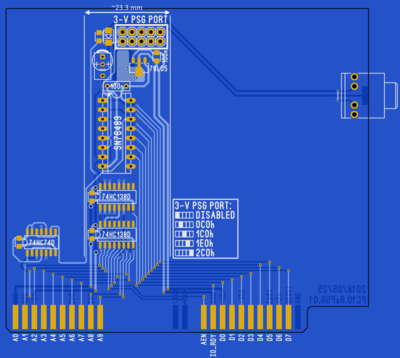
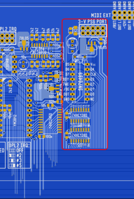
I've already did my own address decoder and alpha version of routing of the "Tandy PSG" block is done.

2018-07-25 01.27.45.png
Filename
2018-07-25 01.27.45.png
File size
15.27 KiB
Views
1401 views
File license
Fair use/fair dealing exception
2018-07-25 01.27.28.png
Filename
2018-07-25 01.27.28.png
File size
65.15 KiB
Views
1401 views
File license
Fair use/fair dealing exception

Muting PSG's output at startup is not done yet.

New BIG soundcard: FMonster.
Covox Sound Master replica
Innovation SSI-2001 replica & DuoSID.
My audio/video collection.

Reply 49 of 275, by Scali

User metadata
Rank l33t
Rank
l33t
Tiido wrote:

The main thing is that almost all the YM chips take one access every half sample or so, writing things faster results in old value that is still pending getting overwritten with new stuff. Sample rate of YM in PC is 3.579545 / 72 = 49715.902777...KHz.
Later OPL3 chip runs at 4x the clock and has bus interface reworked a bit so it has much smaller delays and even later OPL3L adds fully buffered register set so you can write things to the chip once every chip clock or two clocks so essentially no delays are needed at all.

I believe I read somewhere that in order to save cost and reduce complexity, Yamaha 're-uses' a single block of oscillator-logic for many channels, so it processes the channels one at a time, in a serial fashion. This would explain why it takes so long for new data to finish processing in the chip.

http://scalibq.wordpress.com/just-keeping-it- … ro-programming/

Reply 50 of 275, by matze79

User metadata
Rank l33t
Rank
l33t

EDIT: wrong. 😁

i simply mute the amp with the attiny13, but you can also just cut the output with the same firmware e.g. using a opto coupler like dreamblasters tandlpt will do.
i enable the amp with the CE Signal. if CE occures, output is enabled.
ISA Reset is also connected to the Tiny13 and on reset it remutes.
One Limitation is if you use the SN76489 at 0C0h and your bios access 0c0h Sound will enable during boot.
This can be avoided by a simple delay.

'ATtiny13 lm386 control
$regfile = "attiny13.dat"
$crystal = 1200000
$hwstack = 8
$swstack = 4
$framesize = 4
Config Portb.4 = Output
'Config Portb.3 = Output
Mute Alias Portb.4
Config Pinb.2 = Input
Config Pinb.0 = Input
Portb.3 = 1
Portb.2 = 1
Isareset Alias Pinb.0
Impuls Alias Pinb.2

Dim Poweron As Integer
Reboot:
Poweron = 0
Mute = 1
Waitms 10000

Do
If Isareset = 1 Then Goto Reboot
If Impuls = 0 Then Poweron = 1
If Poweron = 1 Then Mute = 0 Else Mute = 1
Loop

End

who does a big card like that can afford a 3$ ISP too i'm pretty sure 😁

https://www.retrokits.de - blog, retro projects, hdd clicker, diy soundcards etc
https://www.retroianer.de - german retro computer board

Reply 51 of 275, by matze79

User metadata
Rank l33t
Rank
l33t

Ah forget, you may want to add a bus driver to the SN76489.
It has noise when its driven directly.

i own the lo-tech tandy board and the sound has always noise inside.
did some experiments and its 100% eliminated by driving the data lines with a 74HC244.

https://www.retrokits.de - blog, retro projects, hdd clicker, diy soundcards etc
https://www.retroianer.de - german retro computer board

Reply 52 of 275, by Fagear

User metadata
Rank Member
Rank
Member
matze79 wrote:

This is not PSG, PSG is a Chip with DAC and 3 Voice.

How do you call that chip then? "Tandy 3-voice Synth", "Tandy 1000/PCjr-like Synth" is far too long.

matze79 wrote:
i simply mute the amp with the attiny13, but you can also just cut the output with the same firmware e.g. using a opto coupler l […]
Show full quote

i simply mute the amp with the attiny13, but you can also just cut the output with the same firmware e.g. using a opto coupler like dreamblasters tandlpt will do.
i enable the amp with the CE Signal. if CE occures, output is enabled.
ISA Reset is also connected to the Tiny13 and on reset it remutes.
One Limitation is if you use the SN76489 at 0C0h and your bios access 0c0h Sound will enable during boot.
This can be avoided by a simple delay.

I try to avoid any programmable devices on my card, because it increases level of difficulty for assembling the card. Firmware can be lost, MCU can become discontinued. 74 series logic isn't going anywhere in the future. It is cheap and does not need programming.
Hell, I can use PAL/GAL or even FPGA to do all decoders, buffers and glue logic. That is not what this card is all about.

For the time I'm looking on combination of D-trigger and analog switch at the output of the 76489. To reduce the size I've chosen 74LVC1G175 and 74LVC1G3175 in SOT23-6.

matze79 wrote:
Ah forget, you may want to add a bus driver to the SN76489. It has noise when its driven directly. […]
Show full quote

Ah forget, you may want to add a bus driver to the SN76489.
It has noise when its driven directly.

i own the lo-tech tandy board and the sound has always noise inside.
did some experiments and its 100% eliminated by driving the data lines with a 74HC244.

Hey, thank you for that info!
One of my goals is to create as cleanly sounding card as possible, so I'll keep that in mind. I think I'll through another 74HC245 for that, so I will not increase BOM with odd 244.

New BIG soundcard: FMonster.
Covox Sound Master replica
Innovation SSI-2001 replica & DuoSID.
My audio/video collection.

Reply 53 of 275, by matze79

User metadata
Rank l33t
Rank
l33t
Fagear wrote:
matze79 wrote:

This is not PSG, PSG is a Chip with DAC and 3 Voice.

How do you call that chip then? "Tandy 3-voice Synth", "Tandy 1000/PCjr-like Synth" is far too long.
i just mistaken it with PSSJ 😀

i'm really intressed how you will make it silent 😁
i also tried with a flipflop but the bios enabled it during boot because of 0c0h are the second dma controller.
thats why i switched to mcu. i wanted to keep it very simple 😀
it worked well with other adresses.

i had the idea to use a ne555 delay.. but ommited that.

https://www.retrokits.de - blog, retro projects, hdd clicker, diy soundcards etc
https://www.retroianer.de - german retro computer board

Reply 54 of 275, by Fagear

User metadata
Rank Member
Rank
Member
matze79 wrote:

i also tried with a flipflop but the bios enabled it during boot because of 0c0h are the second dma controller.
thats why i switched to mcu. i wanted to keep it very simple 😀
it worked well with other adresses.

Would you even use Tandy on port 0x0C0 if you have DMA there?
Also, were those writes exatly at 0x0C0 or maybe it was another address from 0x0C1 to 0x0C7? Because lo-tech board puts the same register on 0x0C0...0x0C7, even if only 0x0C0 is required. My decoder limits it to 0x0C0...0x0C1.
Did you count how many times 0x0C0 was accessed during boot? Probably something like divider/counter on /CS will help? Wait for 2 or 4 accesses from reboot before unmuting.

New BIG soundcard: FMonster.
Covox Sound Master replica
Innovation SSI-2001 replica & DuoSID.
My audio/video collection.

Reply 55 of 275, by Scali

User metadata
Rank l33t
Rank
l33t
Fagear wrote:

Would you even use Tandy on port 0x0C0 if you have DMA there?

I have it like that in my 286 clone, and the sound card works fine that way. Second DMA won't work, but I don't use it for anything anyway.

Fagear wrote:

Also, were those writes exatly at 0x0C0 or maybe it was another address from 0x0C1 to 0x0C7? Because lo-tech board puts the same register on 0x0C0...0x0C7, even if only 0x0C0 is required. My decoder limits it to 0x0C0...0x0C1.

That was a specific design choice, because the PCjr has the same address decoding to C0-C7. I believe the same goes for Tandy.

My Philips 8088 clone also writes to the C0-C7 range on bootup... not sure why, because it doesn't have a second DMA controller of course.

http://scalibq.wordpress.com/just-keeping-it- … ro-programming/

Reply 56 of 275, by matze79

User metadata
Rank l33t
Rank
l33t

i run tandy audio card in 486DX2 50Mhz and have no problems, it works well at 0c0h.
Also runs in my 386SX Triumph Adler Machine.

i had no logic probes connected to see what happens.
And i only have these cheapo cypress logic analyzer from china wiring this up is annonying 😀

https://www.retrokits.de - blog, retro projects, hdd clicker, diy soundcards etc
https://www.retroianer.de - german retro computer board

Reply 57 of 275, by Fagear

User metadata
Rank Member
Rank
Member
Scali wrote:

That was a specific design choice, because the PCjr has the same address decoding to C0-C7. I believe the same goes for Tandy.

Yes, I know. Those just don't decode 3 LSBs. But it is not necessary, PSG has just one register, that should be at 0x0C0. At least I didn't see any software, that was patched in that thread, that used other port except of 0x0C0.
I think more narrow address window can help avoiding conflicts with other hardware. At any rate, I always can disconnect A1 and A2 from decoder, converting it into 0x0C0...0x0C7 address pool.

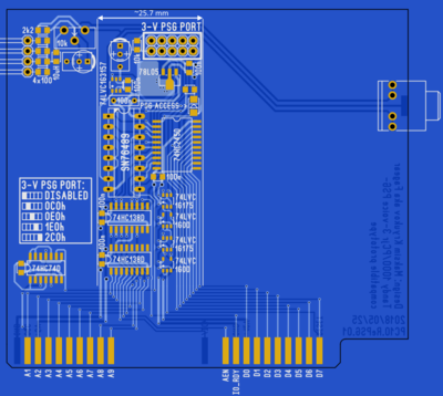
I've taken matze79's advices into consideration and made design changes.
Before:

3VPSG_2018-05-25_01.png
Filename
3VPSG_2018-05-25_01.png
File size
34 KiB
Views
1324 views
File license
Fair use/fair dealing exception

After:

3VPSG_2018-05-25_02.png
Filename
3VPSG_2018-05-25_02.png
File size
53.37 KiB
Views
1324 views
File license
Fair use/fair dealing exception

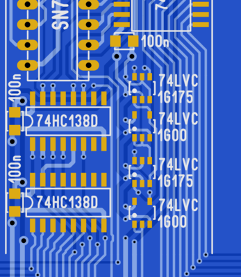
There is some tiny stuff:

3VPSG_2018-05-25_03.png
Filename
3VPSG_2018-05-25_03.png
File size
45.09 KiB
Views
1324 views
File license
Fair use/fair dealing exception

Those are two NAND gates and two D-triggers. I've tried to put a 74HC74 (two D-triggers) but it just didn't fit in that space. So I've put two tiny 74LVC1G175 - one D-trigger, but somewhat cut down: there is no /PRE input and /Q output. So I've had to put not one inverter, but two. NAND gate is always can be more useful, than just a NOT gate and you can easily made NOT out of NAND, so that is exactly what I did. One 74LVC1G00 is inverting RESET signal from ISA bus, the other takes place of missing /Q output of the trigger.
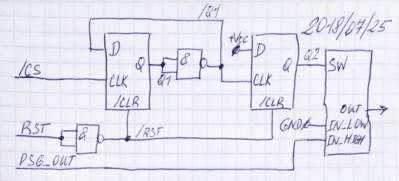
Output of all these goes to analog switch 74LVC1G3157 that selects between ground and output from synth IC. Switch is configured to disable output (switch it to ground) if low-level signal is present.

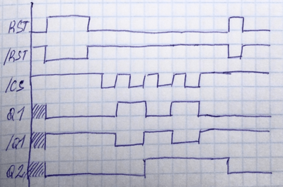
I've tried to draw a scheme and a time diagram:

3VPSG_mute_01.png
Filename
3VPSG_mute_01.png
File size
408.29 KiB
Views
1324 views
File license
Fair use/fair dealing exception
3VPSG_mute_02.png
Filename
3VPSG_mute_02.png
File size
307.15 KiB
Views
1324 views
File license
Fair use/fair dealing exception

I think that if there is a "wrong" write to 0x0C0, that it will be the only one (maximum two ones) on the start (I have yet to order, assemble the debug board and check for myself).
So chain of two D-triggers provide me a two-CS-cycles delay before enabling audio output while providing non-restricted access to the synth IC itself. Even if there will be no "wrong" writes - in either way you have to do some writes first to initialize the chip before playing sound. So delayed mute circuit should not make any harm.

While adding that "mute circuit" and bus buffer I've managed to increase "length" of the 3V-PSG block just by 2.5 mm! 😎

New BIG soundcard: FMonster.
Covox Sound Master replica
Innovation SSI-2001 replica & DuoSID.
My audio/video collection.

Reply 58 of 275, by carlostex

User metadata
Rank l33t
Rank
l33t
matze79 wrote:

Maybe some one can put a Covox Soundcard on a X-ray Scanner 😁

So all traces should be visible without destroying it ?

Only member that can do that is moturimi1. Other owner is Yvan256 but we haven't heard from him in a while.

What i'm hoping is that shock__ can have access to moturimi1's card and help Fagear with tracing what's left to be traced. That's not everything that needs to be done though, there is a PAL chip on the Covox Sound Master that needs to be probed and then its function replicated either by a GAL or some 74 series logic.

One of the things i've been wondering is how difficult it would be to clone an IBM Music Feature Card. There would be absolutely no need to replicate the MIDI interface on the card which would greatly simplify it. I don't know about parts availability but at least the YM2164 FM chip seems to be available in UTSOURCE. Get rid of the MIDI interface, just keeping the sound capabilities and another rare sound option biting the dust. Imagine 5 rare sound cards in one:

- CMS;
- Innovation SSI-2001;
- Covox Sound Master;
- 3 voice Tandy sound card;
- IBM Music Feature;

Hypothetically even replicating an AdLib Gold is possible, providing all the parts are still available and we can find out everything that big GOLD CTRL chip does.

EDIT: Out of morbid curiosity the YMZ263-F MMA chip seems to be available in high numbers.

Reply 59 of 275, by Scali

User metadata
Rank l33t
Rank
l33t
carlostex wrote:

One of the things i've been wondering is how difficult it would be to clone an IBM Music Feature Card. There would be absolutely no need to replicate the MIDI interface on the card which would greatly simplify it.

You can't get rid of the MIDI interface, unless you want to move it into software.
Namely, the IMFC is basically the same thing as a Roland LAPC-I card: it's a MIDI interface with a MIDI module connected to it.
The YM2164 cannot be accessed directly by the host. It contains a Z80 processor and its own firmware, and is basically a Yamaha FB-01 module.
The only way to access it is via the MIDI interface (the interface is connected both to the onboard FB-01 module and the external MIDI ports).

Cloning a full FB-01 is probably quite difficult, it's a rather complex device. However, they are very cheap secondhand.
And I have already created 'SoftIMFC', which is basically the IMFC equivalent of SoftMPU: it will use EMM386's port virtualization to emulate the IMFC's MIDI interface, and redirect it to an MPU-401 UART compatible or SB MIDI compatible MIDI port. Just connect an FB-01, and you have an IMFC-compatible system: https://github.com/Scalibq/FB-01-Emulator/tre … master/SoftIMFC

I am also working on emulating the FB-01 itself in software, similar to MUNT. Combine that with SoftIMFC or my IMFC-code for DOSBox, and you can have full IMFC emulation in software.
Sadly, the FB-01 emulation isn't very mature yet... It plays the right notes, but that's about it. The instrument configuration is way off.

http://scalibq.wordpress.com/just-keeping-it- … ro-programming/