VOGONS


First post, by bakemono

User metadata
Rank Oldbie
Rank
Oldbie

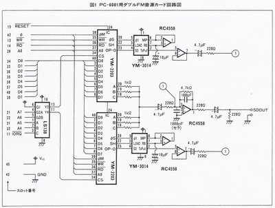
So... I designed my first PCB (not counting the homework assignment I had one time where I had to lay out a circuit on a piece of graphing paper). What is it? Well, it's basically an EPROM and a YM2203 on an 8-bit ISA card. The reason I did that is because I felt that an EPROM alone would be too easy and boring, even if it is potentially useful, while the YM2203 was more interesting but not very practical since there is no PC software that uses it. Plus, I wasn't sure if I'd be able to get it to work. In particular I didn't really know what to do with the audio output and the Y3014, as you can see I didn't put in an audio jack or amplification, just a 4-pin header to run to the aux input of another sound card.

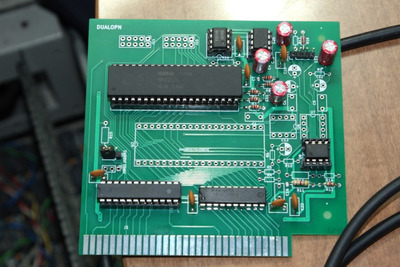
As for the board layout, in retrospect many of the traces probably could have been routed more easily by packing them closer together. But I just aligned them according to the grid pitch which was based on the distance between pins on the ICs. Looking at the final product, it somehow seems a lot less complex than it did on the screen when I was continually running traces and then deleting them and running them a different way. The decoupling caps and power/gnd are a bit haphazard, in fact one of the capacitors is missing. I accidentally deleted it in pcbnew and didn't know how to get it back... Later when I checked VCC with a scope probe it didn't look bad, maybe it's fine.

I submitted the gerber files and then after receiving the boards I ordered various components. I soldered everything on, and the first test I did was in a 486 board, with ROM installed but without the FM enabled. The jumpers on the board allow mapping the ROM to C800/D000/D800 and mapping the FM to 180/1C0/380. I left off the jumper for the FM at first, to test the ROM. This worked. Yay 😀 Then I tried it with the FM jumper installed, aaaaand the computer didn't boot 🙁

Turns out I made a mistake in the address decoding. If a memory read happens at an address which matches the FM I/O range then the 74245 activates and tries to drive the bus. Oops. I could fix this with a few wires, but as a temporary fix I just lifted a certain IC pin which effectively disabled the ROM but allows the FM to be accessible.

I think the YM2203 is usually clocked at 3-4MHz? There is nothing like that on the ISA slot. The datasheet said something about dividing the clock by 6, so I thought maybe 14MHz divided by 6 would work so that's how I connected it. Perhaps not. When I installed the card in my 286 and tried to access the FM, I was able to read and write registers which is good. I didn't check the timer IRQ. I briefly tried the PSG audio which did not work, probably because pin 17 is supposed to be connected to something. *shrug* As for FM synthesis, I went into QBASIC and fed it some data from a GYM file. There was a faint, heavily distorted sound coming out. I thought I had to write to a register to enable the clk/6 divider, but it didn't seem to do anything. I couldn't find more info about it, but then I found a YM2608 datasheet which said that the clk/6 mode is the default one. I checked the clock coming out of the YM2203 going to the Y3014 and it was 4.7MHz which I'm sure is too fast.

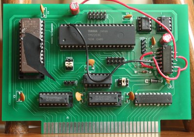
Trying to come up with an alternative plan, I eventually found out how to make a divider using a 74F74 which I harvested from a junk motherboard. That's the thing with all the red wires. Now I have a 3.58MHz clock going into the YM2203. So I tried to play a GYM file again, the sound is somewhat more recognizable but still very distorted, like it has massive clipping.

For a first board that is partially working I consider this a win 😀 Someday I'll have to learn about opamps and stuff though...

Attachments

  • wtcard.jpg
    Filename
    wtcard.jpg
    File size
    391.33 KiB
    Views
    979 views
    File license
    Fair use/fair dealing exception

Reply 1 of 8, by shock__

User metadata
Rank Oldbie
Rank
Oldbie

Gotta have to start somewhere 😀

While I never learned PCB design, I'd call this extremely good for a first PCB. Sure it has it's botches and kinks, but so do mine still after 7 projects. Looking forward to see how the final product looks like if you decide to make it more than a personal project at one point.

The only thing that really pops into my eye, but is totally irrelevant is the fact that one could probably easily plug in the board with the wrong polarity, which is more of an issue with how ISA8 and the backplate are concepted.

Last edited by shock__ on 2019-07-18, 20:37. Edited 1 time in total.

Current Project: new GUS PnP compatible soundcard

[Z?]

Reply 3 of 8, by matze79

User metadata
Rank l33t
Rank
l33t

at least you get some tunes out of it.
Don`t give up 😀 some times it takes a few iterations of a pcb to get it right.

https://www.retrokits.de - blog, retro projects, hdd clicker, diy soundcards etc
https://www.retroianer.de - german retro computer board

Reply 4 of 8, by bakemono

User metadata
Rank Oldbie
Rank
Oldbie

Yeah, I have to try some more modifications when I get time. Adding a resistor here or capacitor there might be able to clean up the sound. I did find this schematic diagram for a YM2203 board so I have something to learn from.

Attachments

  • ym2203d.jpg
    Filename
    ym2203d.jpg
    File size
    143.83 KiB
    Views
    794 views
    File license
    Fair use/fair dealing exception

Reply 5 of 8, by root42

User metadata
Rank l33t
Rank
l33t

Great work! Incidentally someone seems to have reverse engineered the IC itself:

https://github.com/galibert/ym2203

YouTube and Bonus
80486DX@33 MHz, 16 MiB RAM, Tseng ET4000 1 MiB, SnarkBarker & GUSar Lite, PC MIDI Card+X2+SC55+MT32, OSSC

Reply 6 of 8, by Tiido

User metadata
Rank l33t
Rank
l33t

This is a very nice effort ~

The schematic you found should work nicely, just dont forget to give the opamps both positive and negative power rails, connecting one between only 5V and GND will result in problems unless you use rail to rail IO type opamps. Normal opamps will not be able to accept full scale input or produce full scale output, they'll always be at least 2V away (1V on top, 1V on bottom). All the schematics in datasheet etc. assume full +/-15V for the analog section. On PC you get +/-12V that will be adequate but it is advisable to regulate it down to 9...10V with linear regs to reduce various noises in those rails.

SirNickity wrote:

I've found the quickest way to discover layout and logic mistakes is to order PCBs...

There needs to be a PCB order simulator 🤣

T-04YBSC, a new YMF71x based sound card & Official VOGONS thread about it
Newly made 4MB 60ns 30pin SIMMs ~
mida sa loed ? nagunii aru ei saa 😜

Reply 7 of 8, by Stiletto

User metadata
Rank l33t++
Rank
l33t++
root42 wrote:

Great work! Incidentally someone seems to have reverse engineered the IC itself:

https://github.com/galibert/ym2203

That's Olivier Galibert, best known in our circles for his two decades of work on MAME. 😀

"I see a little silhouette-o of a man, Scaramouche, Scaramouche, will you
do the Fandango!" - Queen

Stiletto

Reply 8 of 8, by bakemono

User metadata
Rank Oldbie
Rank
Oldbie

I had another go at this, incorporating lessons learned and whatnot. As you can see, there is provision for two chips and I packed it all into a smaller space 😀 Right now I only have one Y3014B (borrowed from a Sound Blaster 2.0) so I installed enough parts to test one chip.

edit: I had to add a couple of resistors and now it is working great. Sample recordings: (playing VGM files on my 286)
http://www.hyakushiki.net/misc/opn/opn1.ogg
http://www.hyakushiki.net/misc/opn/opn2.ogg
http://www.hyakushiki.net/misc/opn/opn3.ogg
http://www.hyakushiki.net/misc/opn/opn4.ogg
http://www.hyakushiki.net/misc/opn/opn5.ogg

Attachments

again another retro game on itch: https://90soft90.itch.io/shmup-salad