VOGONS


Voodoo 5 5500 AGP freezes PC

Topic actions

Reply 20 of 28, by Justin1091

User metadata
Rank Member
Rank
Member
PCBONEZ wrote:

Before we go much further have you tried different firmwares?
I dunno which are good or bad. Just know there are more than one.
.

Yeah, the bad one has 1.06 AGP. Good one also came with this version, I did update it to 1.18 years ago.
Also updated the bad one years ago, didn't help.

Reply 21 of 28, by PCBONEZ

User metadata
Rank Oldbie
Rank
Oldbie
Justin1091 wrote:

What do you mean with ground plane?

Justin1091 wrote:

If I understand correctly there should be a place on the card that is the ground plane, but I can't find it.

Sorry. you did so well with the caps that I assumed you knew that stuff.
I will try to find a tutorial online and if not I'll make some drawings. (I need to explain via's too.)

Just basically a ground plane like a trace but it's more like a sheet of copper than a strip.
It might be on the top layer or it might be between PCB layers where you can't see it.
They use them for several reasons.
- Ground (and sometimes some voltage) is needed all over the place so for distribution.
- The copper spreads the heat around better than the PCB material to prevent hot spots.
- It reduces EMI and cross-talk for better signal quality. Same idea as when they increased IDE speeds by adding 40 ground wires between the original 40 wires.

Justin1091 wrote:

Is the card's pci bracket sufficient for ground?

Sometimes good, sometimes not.
They don't always ground the screw holes and sometimes the plating screws things up.
If you get zero resistance to the grounds in the power conn. it's probably okay.

-
The last couple inches of the card opposite the bracket is all DC-to-DC converters.
I know from the VSA100 datasheet you found that the highest voltage it uses is 3.3v.
It makes sense that the converters are making 3.3v and it gets distributed all over the card.
12v -> 3.3v and 5v -> 3.3v (And the two outputs appear to be Siamesed into one 3.3v rail.)

Great find on the datasheet BTW. I knew I'd seen it a long while ago but I couldn't find it again.
.

Last edited by PCBONEZ on 2018-05-11, 00:36. Edited 1 time in total.

GRUMPY OLD FART - On Hiatus, sort'a
Mann-Made Global Warming. - We should be more concerned about the Intellectual Climate.
You can teach a man to fish and feed him for life, but if he can't handle sushi you must also teach him to cook.

Reply 22 of 28, by PCBONEZ

User metadata
Rank Oldbie
Rank
Oldbie

The two center pins in your power connector are ground.
So long as the card isn't using a floating ground (which would be rare) they should be connected to the ground plane.
I would expect it to be zero ohms between the two center pins and the negative sides of the small lytic caps.
.

GRUMPY OLD FART - On Hiatus, sort'a
Mann-Made Global Warming. - We should be more concerned about the Intellectual Climate.
You can teach a man to fish and feed him for life, but if he can't handle sushi you must also teach him to cook.

Reply 23 of 28, by PCBONEZ

User metadata
Rank Oldbie
Rank
Oldbie

.
The number of Layers pertains to the number of laminate layers that have conductors.
Vias are just holes that have been plated to be conductors into/through the board.
2 layer PCBs and up can have Vias.
On PCBs 3 layers and up the Vias don't always surface on both sides due to internal connections.
.
I imagine that card is 2 or 3 layers. Motherboards are usually 4 to 6 layers.
.

Bonezicon_VIA_Layer_.JPG
Filename
Bonezicon_VIA_Layer_.JPG
File size
83.75 KiB
Views
941 views
File license
Fair use/fair dealing exception

.

GRUMPY OLD FART - On Hiatus, sort'a
Mann-Made Global Warming. - We should be more concerned about the Intellectual Climate.
You can teach a man to fish and feed him for life, but if he can't handle sushi you must also teach him to cook.

Reply 24 of 28, by PCBONEZ

User metadata
Rank Oldbie
Rank
Oldbie
5500_pwr_1.jpg
Filename
5500_pwr_1.jpg
File size
158.6 KiB
Views
938 views
File license
Fair use/fair dealing exception

.
I don't think the power section is the problem because the chips are clearly getting 3.3v power but we need to know where the 3.3v originates to track down problems deeper in the card.
As far as the chips are concerned 3.3v is the power source.
.
I did not notice the little "+" signs in the area I marked 3.3v plane earlier so I wasn't sure which side was ground and which +.
.

GRUMPY OLD FART - On Hiatus, sort'a
Mann-Made Global Warming. - We should be more concerned about the Intellectual Climate.
You can teach a man to fish and feed him for life, but if he can't handle sushi you must also teach him to cook.

Reply 25 of 28, by PCBONEZ

User metadata
Rank Oldbie
Rank
Oldbie

.
Inside the turquoise box is a surface ground plan. There may be others.
The green boxes inside that are islands with something other than ground.
L20 & L21 are not connected to ground. They jump over as do the resistors just below them.

5500_pwr_3.JPG
Filename
5500_pwr_3.JPG
File size
188.32 KiB
Views
934 views
File license
Fair use/fair dealing exception

In regards to Q5's pins/pinout.

Q5.jpg
Filename
Q5.jpg
File size
11.91 KiB
Views
934 views
File license
Fair use/fair dealing exception

.

Last edited by PCBONEZ on 2018-05-11, 15:15. Edited 1 time in total.

GRUMPY OLD FART - On Hiatus, sort'a
Mann-Made Global Warming. - We should be more concerned about the Intellectual Climate.
You can teach a man to fish and feed him for life, but if he can't handle sushi you must also teach him to cook.

Reply 26 of 28, by PCBONEZ

User metadata
Rank Oldbie
Rank
Oldbie

.
The vias shown in yellow have no continuity out of their area on the surface on either side.
It has to be at least a 3 Layer board or none of those go anywhere.
.

5500_Front-Back_01.jpg
Filename
5500_Front-Back_01.jpg
File size
76.61 KiB
Views
934 views
File license
Fair use/fair dealing exception

GRUMPY OLD FART - On Hiatus, sort'a
Mann-Made Global Warming. - We should be more concerned about the Intellectual Climate.
You can teach a man to fish and feed him for life, but if he can't handle sushi you must also teach him to cook.

Reply 27 of 28, by Justin1091

User metadata
Rank Member
Rank
Member

Wow, thanks! So with a multi layered pcb like this one, you cannot access the ground plane because it is covered by another layer. So, in order to 'touch it, one can use for example the ground pins on the molex connector (which I did just now).

Here are the results from the test points (voltages) to gnd:

Bad card

  • TP1: nothing
    TP2: updated: 1.66-1.70v (3d same)
    TP3: nothing
    TP4: nothing
    TP5: 0.01V (3D the same)
    TP6: 1.66-1.70v (3D same)
    TP7 through 11: nothing

Good card

  • TP1:
    TP2: 1.62v(3D same)
    TP3: nothing
    TP4:
    TP5: 0.01 to 0.03 (3D same)
    TP6: 1.62v(3D same)
    TP7 through 11: nothing

Downclocking the card from 166mhz to 133mhz did not show a difference in voltage on those Tp's (my guess was that the 1.66v was linked to 166mhz, it isn't).

Update: also did TP's to 5v and 12v:

Bad card:

  • TP2 to 5v: 3.20v
    TP2 to 12v: 9.88v

    TP5 to 5v: 5V
    TP5 to 12v: 12.24V

    TP6 to 5v: 3.22v
    TP6 to 12V: 9.82

3d no big difference (when it crashes that is). Single chip or dual chip no difference

Good card

  • TP2 to 5v: 3.4v
    TP2 to 12v: 10.55v

    TP5 to 5v: 5v
    TP5 to 12v: 12.18v

    TP6 to 5v: 3.4v
    TP6 to 12v: 10.55v

Now the resistance on the Tp's

  • TP1: nothing
    TP2: 11.86 for good card, 11.90 for bad card
    TP3: nothing
    TP4: nothing
    TP5: nothing
    TP6: 12.42 for good card, 11.16 for bad card
    TP7 through 11: nothing

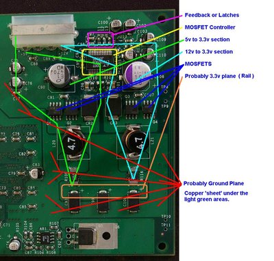
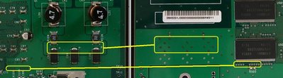
Like you drawed on the picture '3.3V plane' reads 3.0V on the bad card. 2.8V on the good card.

To the left of C91 a small hole reads 5V for both cards. Near R115 reads 3.3V for both cards. Near R114 reads 6v for the good card, 6.4v for the bad one.
I couldn't find a 12v.

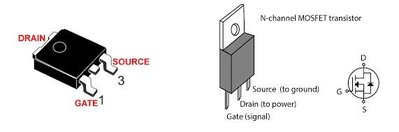
Bad card Q1-Q4 to gnd
Q1 0.5v 1 side 3.0v other side
Q2 1.75v to 3.0v
Q3 3.5v to 3.0v
Q4 12v to 3.0v

Good card Q1-Q4 to gnd
Q1 0.5v to 2.8v
Q2 1.9v to 2.8v
Q3 3.5 to 2.8v
Q4 12v to 2.8v

So it looks like the bad card has 3.0v on places and the good card 2.8v

Q6 reads 3.32V for both cards (metal plate)

All replaced caps have continuity with the ground pins on the molex connector.

Update: I believe I found what U4 (NJA) is: TPS3801J25DCK 2.25 V ULTRA-SMALL SUPPLY VOLTAGE SUPERVISORS (Texas Instruments)
http://www.hk-electronics.com/components/Lumi … 1J25DCKRG4.html

Last edited by Justin1091 on 2018-05-20, 20:52. Edited 1 time in total.

Reply 28 of 28, by PunishedSnake

User metadata
Rank Newbie
Rank
Newbie
Justin1091 wrote:
Hi guys, […]
Show full quote

Hi guys,

I have a Voodoo 5 5500 AGP videocard which I haven't used for a couple of years. Back then, I got it from eBay and it never worked properly so I got another one which works.

However, after this time I thought I'd look into it's problems again, so maybe someone of you can help me.

The card works fine in Windows, the issue is that the computer locks up when running 3D games (or the dxdiag.exe D3D test which is easy to run). When running the card in 'Single Chip Only' mode it works fine.
I noticed something strange: when using a third party driver like Amigamerlin's you get access to more options in 3dfx tools, like 'Guardband Clipping', Disabling this feature made the card run with two chips back then, I didn't have time to test it now.

What I did today was look at the card and I noticed a capacitor had a dent in it, the big one near the molex connector top right of the card. I replaced it but that didn't work. Still the same issue.

Does anyone know of something else to check or rule out? I don't believe it's the gpu chips, as they can function with the guardband clipping feature off (at least back then, I will try it again in a couple of days).
I have uploaded some pictures of the card, maybe someone can see if something is wrong. The only things I see is CR1 (near the molex connector) which is not straight. No idea what it even is. The other thing is R112, which has a color, unlike the other ones R111 and R113.
Other Voodoo5 cards I saw on Google Images didn't have either of these two things.

https://imgur.com/a/9ovsLMo

Hey mate, just to be clear, guardband clipping=ON works fine also on your other card with both VSA-100s enabled but not this one? And it only happens on all drivers if guardband clipping is enabled for D3D? FYI Guardband clipping can and should be disabled anyway and you don't need AmigaMerlin to tweak that, download V.Control from falconfly and test with driver V1.04.00. It's really odd as to my understanding the settings within the 3DFX control panel shouldn't flow across to 3DFX DOS games, they're only meant to use settings within the SET environment variables.

P.S. Mods, sorry to necropost, but I'm unable to respond to Justin1091's PM regarding the issues he's been having due to my low post count.