VOGONS


Reply 140 of 200, by root42

User metadata
Rank l33t
Rank
l33t

The biggest costs are the ET4000W32i chip (I paid 20€ per piece after customs from questcomp), the RAM and the RAMDAC. PCBs are less than 10€ at JLC. At the moment a full kit is roughly 100€.

If we can get the ET4000 chips for cheaper that would help. But I doubt we get it lower than 80-90€ BOM cost. When assembled it will be more costly if the one who does the assembly isn't doing it for free.

YouTube and Bonus
80486DX@33 MHz, 16 MiB RAM, Tseng ET4000 1 MiB, SnarkBarker & GUSar Lite, PC MIDI Card+X2+SC55+MT32, OSSC

Reply 141 of 200, by ltning

User metadata
Rank Member
Rank
Member
root42 wrote on 2021-06-23, 08:09:

If we can get the ET4000 chips for cheaper that would help. But I doubt we get it lower than 80-90€ BOM cost. When assembled it will be more costly if the one who does the assembly isn't doing it for free.

And how much time does assembly take - roughly, and after one or two successful builds for practice? I still don't think this sounds awful, given that it would provide one of the best possible graphics solutions for ISA-class machines with none of the usual issues with such old hardware.

If assembly takes a couple of hours then I'm definitely game. If it's days of work then .. well. maybe not. :)

/Eirik

The Floppy Museum - on a floppy, on a 286: http://floppy.museum
286-24/4MB/ET4kW32/GUS+SBPro2
386DX-40/20MB/CL5434 ISA/GUSExtreme
486BL-100/32MB/ET4kW32p VLB/GUSPnP/AWELegacy

~ love over gold ~

Reply 142 of 200, by root42

User metadata
Rank l33t
Rank
l33t
ltning wrote on 2021-06-23, 08:17:

And how much time does assembly take - roughly, and after one or two successful builds for practice? I still don't think this sounds awful, given that it would provide one of the best possible graphics solutions for ISA-class machines with none of the usual issues with such old hardware.

If assembly takes a couple of hours then I'm definitely game. If it's days of work then .. well. maybe not. 😀

Depends on your proficiency. There are 5 non-trivial SMD components (ET4000 QFP, 4x RAM TSSOP). I had those soldered by a friend, because I am not very good at SMD component soldering yet. Then you have ~100 other components. Depending on your skill and attention to detail this takes 2-6 hours.

YouTube and Bonus
80486DX@33 MHz, 16 MiB RAM, Tseng ET4000 1 MiB, SnarkBarker & GUSar Lite, PC MIDI Card+X2+SC55+MT32, OSSC

Reply 143 of 200, by superfury

User metadata
Rank l33t++
Rank
l33t++

Hmmm... Do you guys get any issues when running the MS-DOS prompt from Windows 3.1(1) in fullscreen mode and switching back to (accelerated) GUI mode? It's giving me a black screen (seemingly hang) doing this?

It runs fine until returning from full-screen text mode? Perhaps a CPU emulation problem?

Author of the UniPCemu emulator.
UniPCemu Git repository
UniPCemu for Android, Windows, PSP, Vita and Switch on itch.io

Reply 144 of 200, by mkarcher

User metadata
Rank l33t
Rank
l33t
superfury wrote on 2021-04-16, 17:36:

Below 1MB it seems simple(upper pins are cleared), but when addressing past 1MB, 8-bit cards would read an address below 1MB instead? Thus incorrectly decoding addresses(e.g. 1A0000 would map to VRAM?)?
Anyone knows what happens on the ISA slot in this case?

This one is quite simple to answer: There are two MEMW/MEMR pins: The AT MEMW/MEMR pins on C9/C10, which are active for memory access between 0MB and 16MB, and the old XT MEMR/MEMW pins (nowadays called SMEMW/SMEMR pins) on B11/B12. The XT pins that are used for 8-bit cards are only active if the target address is below 1MB. So an write to 1A0000 would activate MEMW on C10, but not SMEMW on B11. A video write to A0000 on the other hand would activate both signals. So for 8-bit card, cycles accessing 1A0000 look like the bus is idle. The card won't respond.

Reply 145 of 200, by root42

User metadata
Rank l33t
Rank
l33t

@ALEKS: I measured the signal on the top resistor array. It was 10 MHz, so I guess my 200MHz scope should be able to show it in at least somewhat reasonable detail. I think the signal looks a bit wavy with a pretty slow rising signal, almost sawtooth like. And there is this small bump at the bottom.

For comparison I also attached a sample picture of the 14.1MHz crystal from the motherboard. Looks like a typical crystal signal, I think. 😉

Attachments

YouTube and Bonus
80486DX@33 MHz, 16 MiB RAM, Tseng ET4000 1 MiB, SnarkBarker & GUSar Lite, PC MIDI Card+X2+SC55+MT32, OSSC

Reply 146 of 200, by ALEKS

User metadata
Rank Newbie
Rank
Newbie

The undershoot (lower bump) is caused mainly by a combination of oscilloscope probe (particularly return signal of probe) and PCB transmission line impedance matching and capacitance adjustment.

Slow rise time is caused by resistor array. Once you experimentally go lower then you will be able to see improvements in rise time.

Even a 50 MHz bandwidth oscilloscope will be able to show the refresh signals but a high bandwidh one (250 - 500 MHz) will be able to show very fast rise times for fast signals in a clear fashion. That is why you might not be able to see high speed signals correctly traced on the screen.

Otherwise, welcome to the DIY hard-core area! Hardware debugging at its best. While it is frustrating, it is also very rewarding once you get the system working!

Later edit: The 14 MHz signal looks good but you have to adjust the probe sensing capacitance to get rid of overshoot and undershoot (as much as your probe adjusting trimmer allows).

TX486DLC / 40 MHz | 32 Mb RAM | 16-bit ISA Backplane | Tseng Labs ET4000/W32i 2 Mb | I/O Interface | Audio Interface | PC Speaker Driver | Signal View Interface
3.5" & 5.25" FDD | 4 x 512 Mb CF | HP 82341D Interface | Intel EtherExpress 16

Reply 147 of 200, by mkarcher

User metadata
Rank l33t
Rank
l33t

Series termination usually does not require 300 Ohm resistors. As ALEKS tried at first, 10 Ohm to 33 Ohm are typical values for series termination. Of course, I do believe you that increasing the resistance helps fixing the problems with your board, but if you need that high, the primary purpose of the resistor array seems to be no longer "termination", but "delay". Looking at the scope image by root42, it seems like the slow rise time delays the recognition of "high" on the /CAS lines by 2 to 3 ns. Taking a look at the ET4000/W32i datasheet, chapter 4.9 ("Display Memory Timing - Interleaved"), J15 ("MD in hold time") is the time RAM data need to stay valid from /CAS going high. Depending on memory configuration, Tseng requires 6.3ns or even 11.2ns. On the other hand, the IS41C16257 datasheet specifies "tOFF", the time from /CAS going high to the data lines getting high-Z as just 3ns minimum. Furthermore, "tCLZ" (misspelled as tCLC in the timing diagram) indicating the time from /CAS going low on the other interleaved bank and that other bank outputting stuff to the data bus is specified as 3ns minimum. So the data on the memory bus can get corrupted 3ns after the /CAS transition, which violates the Tseng memory timing specification. Delaying /CAS using the 300 Ohm resistors seems to shift rising /CAS just enough to get enough data hold time.

If the analysis of the previous paragraph is right, the textbook solution might be a non-inverting 74AC541 buffer between the /CAS and /RAS output and the series termination resistor (which might be reduced down 22 Ohms or something like that) providing around 4ns delay to the memory strobe signals. I did not verify whether this suggestion violates other timing constraints, though.

Reply 148 of 200, by ALEKS

User metadata
Rank Newbie
Rank
Newbie

Now that I read it, I think what mkarcher has detailed above is actually what is happening. And that is why increasing the values of RA2 and RA3 allowed for a bigger rise time to make up a "wide-enough" pulse for the refresh circuitry to work properly. This is the most plausible explanation. As I said on my site, once I found a hack (270 R - 300 R) to make the system stable, I lost interrest in finding and understanding the root cause.

But now I am happy mkarcher analyzed the timing diagrams. Indeed the ISSI chips are from another era comparing to the ET4000/W32i chip which would've expected slower tOFF timing.

The solution to use the intrinsic propagation delay of a simple buffer IC is actually very elegant. However I think the non-inverting buffer should be of ACT type though. I will experiment this solution when I will free myself from other projects that I am on at the moment.

In the meantime, just go with 270 R as I did and we'll see if that brings your card to a stable state.

TX486DLC / 40 MHz | 32 Mb RAM | 16-bit ISA Backplane | Tseng Labs ET4000/W32i 2 Mb | I/O Interface | Audio Interface | PC Speaker Driver | Signal View Interface
3.5" & 5.25" FDD | 4 x 512 Mb CF | HP 82341D Interface | Intel EtherExpress 16

Reply 149 of 200, by root42

User metadata
Rank l33t
Rank
l33t

That explanation sounds very reasonable. Waiting for my desoldering station to arrive so I can swap out the resistors...
I guess I will have to acquire more ICs and wait for the next board revision as well. 😀

YouTube and Bonus
80486DX@33 MHz, 16 MiB RAM, Tseng ET4000 1 MiB, SnarkBarker & GUSar Lite, PC MIDI Card+X2+SC55+MT32, OSSC

Reply 150 of 200, by pentiumspeed

User metadata
Rank l33t
Rank
l33t

If possible borrow a quality 100MHz even 1GHz CRT oscilloscope. Keep the ground clipped to very short near measurement point. Also adjust the probe (it has a screw in it) for best quality with the test signal that is present on your scope. Inexpensive scopes is not good to have believe me!

I had to deal with this also, and I had a low quality new scope which does not help! So I gave it away to another tech when business closed, Years later I was given a better scope to use for now.

PS: That signal on second picture is main problem and is not acceptable, You want signal to look more like ramped square wave (trapezoidal actually) , ideally, close to square wave.

Cheers,

Great Northern aka Canada.

Reply 151 of 200, by root42

User metadata
Rank l33t
Rank
l33t

So I replaced the 300 Ohms with 270 Ohms and the artifacts were severly reduced. However it is still not good. Monkey Island 2 has a few noise columns, while Windows has lots of stray pixels. This is still far from usable. I think I will have to chalk this project up to experience... Is there any chance we can get a revised board design? Would be lovely to have. I spent way too much money already, but would love to have a working card!

YouTube and Bonus
80486DX@33 MHz, 16 MiB RAM, Tseng ET4000 1 MiB, SnarkBarker & GUSar Lite, PC MIDI Card+X2+SC55+MT32, OSSC

Reply 152 of 200, by pentiumspeed

User metadata
Rank l33t
Rank
l33t

Get Art of Electronics book. Good tome for designing electronics and any books on designing 50-100MHz buses and signal lines.

And study high speed signal designs that are properly done. Your PCB lacks extra electronic components to guarantee the digital signal quality needed for the chipset, vram and ramdac.

Study the reference book about ET4000AX chipset and their requirements.

Cheers,

Great Northern aka Canada.

Reply 153 of 200, by root42

User metadata
Rank l33t
Rank
l33t
pentiumspeed wrote on 2021-07-08, 20:58:

Get Art of Electronics book. Good tome for designing electronics and any books on designing 50-100MHz buses and signal lines.

And study high speed signal designs that are properly done. Your PCB lacks extra electronic components to guarantee the digital signal quality needed for the chipset, vram and ramdac.

Well, I think I won't pick that hobby up right now. I am fine just soldering the works of others. 😉 It was more a question directed to Alex and hoping he might perfect his creation, which is already nice as it is. Plus since only the Gerbe files are available, it is easiest for him to change the actual PCB design.

YouTube and Bonus
80486DX@33 MHz, 16 MiB RAM, Tseng ET4000 1 MiB, SnarkBarker & GUSar Lite, PC MIDI Card+X2+SC55+MT32, OSSC

Reply 154 of 200, by ALEKS

User metadata
Rank Newbie
Rank
Newbie

pentiumspeed's recommendation is very good (in fact I studied similar books for high-speed PCB design and signal propagation and integrity, which helped a lot for my 80386DX project).
The only drawback is that acquiring new skills takes time and involvement.

Good thing that you progress with the experiments.
One thing is for sure, if the 270 R resistors don't make your card stable (as mine is with 270 R) then there might be a possibility that the Chinese PCB responds differently than the OSH Park one at high speed. Without having one, and measuring one, I can't postulate anything.

Normally, since my card works as expected in my system, there would be little interest from my side to continue with a second revision, as I don't do and nor do I plan to do any business out of this hobby (i.e.: not making any revenue at all).
But since it triggered a lot of interest on the forum, I will research a way to introduce the required 4 ns latency between the integrated DRAM controller and the ISSI chips (the hex buffer idea is good but I need to see what maximum frequency the ACT chip supports and what frequency the DRAM timing signal is running at, otherwise we might dive into other issues). Then I will do another PCB with this upgrade.
However I do have other priorities at the moment (including a bigger project: Pentium 233 MHz / MMX DIY singleboard computer on the ISA bus -- which I think will be out of reach to most hobbyists due to BGA chipset). That means the VGA card will have to wait a bit.
Then again, a new PCB revision will imply first me testing it, and then after checking that it works, I can release the next batch of Gerbers. Unfortunately there will be no source files for my designs.

Can you post some pictures of the screen as it is at the moment, with the new resistor packs?
(in your case, indeed, going lower will further improve, sorry for not being able to directly recommend you the correct resistor value, as I just experimentally adjusted mine directly in system, with the OSH Park PCB and the other parts)

However I still think that you can stabilise the card as it is by experimenting with the resistors. Instead of packs, you could use individual ones like I did for testing purposes. Those are easier to desolder.

PS: x86 system design is not a cheap hobby. What companies with tens of employees and lots of $ invested in research and development did in the '90s, I did in my spare time, with the knowledge acquired also in my spare time throughout the years. Indeed prototyping such stuff comes with some costs (both measured in time and money). The fact is that all components can be recovered. Even the Tseng chip itself. And you don't need any fancy IR heater table. Just a classic electric oven heated to around 220 degrees. If you used lead solder. Otherwise, the required temperature might be higher.
I have mostly recovered all parts of my failed prototypes and reused them on other designs.

Cheers,

TX486DLC / 40 MHz | 32 Mb RAM | 16-bit ISA Backplane | Tseng Labs ET4000/W32i 2 Mb | I/O Interface | Audio Interface | PC Speaker Driver | Signal View Interface
3.5" & 5.25" FDD | 4 x 512 Mb CF | HP 82341D Interface | Intel EtherExpress 16

Reply 155 of 200, by root42

User metadata
Rank l33t
Rank
l33t

I will post some pictures later, when I get the time. The artifacts in mode 13 are severly reduced. In Windows they are still pretty strong.

220 Ohm RPs are on their way, and I will try and use them. Desoldering is easy, thanks to my new desoldering gun. 😉

YouTube and Bonus
80486DX@33 MHz, 16 MiB RAM, Tseng ET4000 1 MiB, SnarkBarker & GUSar Lite, PC MIDI Card+X2+SC55+MT32, OSSC

Reply 156 of 200, by root42

User metadata
Rank l33t
Rank
l33t

@aleks Here is the video of the card in action. While in Windows, I touched the RPs with my fingers to change the resistance, or maybe even impedance? It gets worse when doing that. So I guess I really need to go lower.

https://youtu.be/6MuAR9k9HOc

EDIT: And this is with 0 Ohm (by bridging every other pin)

https://youtu.be/DVeAua_I1rE

As you can see it gets much worse. Touching the upper RP makes it much better, lower RP doesn't seem to do much.

YouTube and Bonus
80486DX@33 MHz, 16 MiB RAM, Tseng ET4000 1 MiB, SnarkBarker & GUSar Lite, PC MIDI Card+X2+SC55+MT32, OSSC

Reply 157 of 200, by ALEKS

User metadata
Rank Newbie
Rank
Newbie

It looks better already with 270 R. You ae close to getting it stable. I'd say 220 R might be too low. But, let's find out how it turns out while mounted in circuit.

PS: Touching the pins alters impedance which is a function of capacitance, resistance, and inductance. So it's hard to pinpoint what parameter variation actually improves or worsens the signal propagation. To a minor extent, various PCBs behave differently. But the variation is tiny, given the fact that OSH Park PCB works spot on with 270 R and yours requires messing around up until you find the sweetspot.

Anyway for the second revision, I will try to make this design more user friendly in terms of reproduction (i.e.: no hardware debugging required).

Cheers,

TX486DLC / 40 MHz | 32 Mb RAM | 16-bit ISA Backplane | Tseng Labs ET4000/W32i 2 Mb | I/O Interface | Audio Interface | PC Speaker Driver | Signal View Interface
3.5" & 5.25" FDD | 4 x 512 Mb CF | HP 82341D Interface | Intel EtherExpress 16

Reply 158 of 200, by pentiumspeed

User metadata
Rank l33t
Rank
l33t

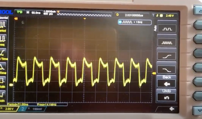
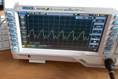
Keep in mind LED current 220 ohm resistors at 5V across both in series is about 22mA. Integrated chipsets might drive high or pull low much more current but these resistors serves to limit the transmission line currents, ringing (think of as echo) and help with keeping heat dissipation of the chipsets, memory, etc. When the waveforms gets distorted, usually this is caused by too high resistance (weak drive), or too low resistance (too many loads on one pin) drives the transistor into saturation (bad!).

Second, switching if there is strong load on it introduces deal of noise due to surges during the low to high and high to low transitions.

Also noise from noisy part get cross polluting to another, hence care of breaking this by "partitioning" each component of the chipset with their own feed and separated circuits into one node with strong capacitors anchoring it.

Art of Electronics book goes into detail about these in turn.

For part of the reason saying about all that, consider this, compaq engineers designing 32 bit expansion memory card broke up the 32 bit memory array into 2 16 chips groups each driven by the RAS line, hence one CAS for all IIRC, and two fo RAS hence means cannot use one 72 pin SIMM soldered into it. So have to wait for funds and order four SIMMs 30 pin 1MB each and wire them in. Lack of 1M x 1bit chips is the main reason.

72pin SIMM based on one bank 1MB, 4MB and 16MB is four CAS, and one RAS. 2MB, 8MB and 32MB uses two RAS lines.

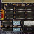
I recently received cirrus logic CL-GD5430 video card with unique designs properly designed in from Russia. I have to post this high resolution photos and backlighted PCB to show the islands too.
No, I didn't design that, it was the the proper designs that I don't see that often in other cards etc made me to purchase it inexpensively.

Second, one time I bought PCI video capture card in 2006 or so and it had herringbone noise in captured videos so I ripped out all the video traces (easy, slice both traces and peel, terminated both ends correctly and installed length of coax cables obtained from cut up quality VGA cable got rid of that noise and gave clean capture. 😀

Cheers,

Great Northern aka Canada.

Reply 159 of 200, by mkarcher

User metadata
Rank l33t
Rank
l33t
pentiumspeed wrote on 2021-07-10, 00:00:

For part of the reason saying about all that, consider this, compaq engineers designing 32 bit expansion memory card broke up the 32 bit memory array into 2 16 chips groups each driven by the RAS line, hence one CAS for all IIRC, and two fo RAS hence means cannot use one 72 pin SIMM soldered into it. So have to wait for funds and order four SIMMs 30 pin 1MB each and wire them in. Lack of 1M x 1bit chips is the main reason.

If COMPAQ just split the RAS line for loading / fan-out reasons into two RAS lines, why don't you just use any one of the two RAS lines? I don't think your 72-pin SIMMs are built of 32/36 1Mx1 chips, so capacitive load shouldn't be a concern for your SIMM.