VOGONS


First post, by starhawk

User metadata
Rank Newbie
Rank
Newbie

Oh dear lord in heaven, starhawk's at it again...

🤣.

I have the analog board out of a Compaq Portable II that didn't make it. (Sorry. Its guts will live on -- they're going to Shelby @ TechTangents on YT.) The yoke is now home to a different tube, although it's also a 9in B&W of about the same era, so it's compatible. I've watched enough of Adrian's Digital Basement to know my way around that one 🤣. It turns out, interestingly, that the Compaq's monitor, internally, isn't actually MDA or CGA, despite being able to display both -- it's mono EGA. This theoretically means I can drive it with VGA timings, using legacy EGA modes, with a half-fistful of resistors to convert RGB color to the single "video" input on the thing. (Yes, I probably could just common the three color leads, but I don't want to do that because reasons.)

I know there were cards, back in the day, that could... overdrive, for lack of a better term, EGA displays, if they were 'multisync' capable, to some pretty decent resolutions. These were called "Extended EGA" modes and were decidedly nonstandard, but did the job regardless. Usually 720x540 was the top end, I believe, but at least one card from a company named NSI claimed to be able to achieve 800x600 (SVGA!!) resolutions. No timing info was given, this being an advertising leaflet that I found, but as this was in the days when 640x480 @ 8bit VGA was juuust beginning to really be meaningful competition, I can't imagine standard SVGA timings are being used here. Honestly, I can't imagine it being anything less than a massive hack job that uses crazy timings and some really dirty circuit tricks to do the work. (However, I am quite open to being wrong about this.)

I'm really not familiar with the term 'multisync', either, but I imagine if it's EGA, but can also do MDA and CGA video feeds, that qualifies, right...? I had an old Samsung that was fixed-resolution VGA, if you tried to feed it absolutely anything that wasn't 640x480 @ 8bits, it got very unhappy very quickly. Like "angry preschooler being told he can't have his favorite Kool-Aid flavor" kinds of unhappy. The kind of unhappy you can hear regardless of where you are in the Wal*Mart. Erm... you get the point, 🤣. So I imagine 'multisync' means... not that? So theoretically I should be able to experiment with the screen I have.

Does anyone know how those "Extended EGA" cards did their thing? Better yet, does anyone have timings, especially for that 800x600 mode from NSI?

Reply 1 of 31, by rmay635703

User metadata
Rank Oldbie
Rank
Oldbie

Um no.

EGA is 25khz
VGA is 31khz

https://forum.vcfed.org/index.php?threads/ega … rtable-1.51290/

Portable II screen switches from
CGA 15khz to
MDA 18khz and doesn’t support true EGA

There were Hercules video cards that could Display 1080x350 (120 column)
on a 5151 MDA monitor the way this is done is by keeping the scan rate the same by slowing or speeding up the individual H&V syncs to stay at the same kHz , possibly scrimping the front and back porch is another trick.

If the screen is analog like vga and allows you to adjust the internal H & V timing there is a small chance you could get it to lock onto vga from a vga card, others have modified the pixel clock on their video card to match and others have used multi-standard vga/EGA cards and set them up properly

Many extended EGA cards required a multi sync monitor and wouldn’t work in hi res on a real 5154.

Good Luck

Reply 2 of 31, by starhawk

User metadata
Rank Newbie
Rank
Newbie

I'm using exactly the electronics you link to, the pinout there is what I've been using to work out an interface board. The plan was to use xrandr or similar plus custom timings -- I'm planning to use a rather newer, but somewhat strange, motherboard with internal graphics (it doesn't have expansion ports for peripheral cards, just FYI) and Xubuntu 18.04. I'm intending to test, however, with an EeePC 1005HA and its external VGA port, as I've not yet purchased the final hardware -- I don't want to buy it if I can't do what I need. I'll be running the same OS on the EeePC for testing.

I'm capable of component-level work if necessary. However, I'm not familiar with the IBM 5151 or the 5154 monitors, and I'm also not familiar enough with 'multisync' as a term to really even understand fully what that denotes.

EDIT: I may not have made this obvious, but I'm only using the analog board and yoke from the Portable II here. The original ISA driver card is no longer present. Instead, the board is going to be getting input from a VGA port on a much newer mobo. The newer board isn't terribly powerful, but it's enough (barely) for what I need and it fits the housing I have in mind. It's a bit weird, is why I'm being coy about exactly what board it is.

I'm using a variation of the circuit in the attached diagram to adapt the VGA signal output from the system board to the monitor -- the resistor pairs on the R and B lines are unchanged, but to get the value for the G resistor pair, as I don't have 9R1 resistors on hand, I'm using two 10R resistors and two 100R resistors in parallel, which gives the same actual resistance. The output from the parallel resistors is then common'd through a pair of Schottky diodes (I have some SR260s on hand, so that's what I'm using) and piped to the 'video' pin on the cable harness to the analog board.

...BTW, there isn't a crystal can on the analog board. The primary control IC seems to be an SGS Thompson branded TDA1170N, and the only other IC is, of all things, a 556 dual timer! I admit I find it rather amusing to see what's now hobbyist-grade parts in a professional setting, although I know things were very different back then.

Attachments

Reply 3 of 31, by rmay635703

User metadata
Rank Oldbie
Rank
Oldbie

I haven’t ever had a need to tear into my original portable but I would check internally for pot adjustments on the tube. If it cannot sync to vga you would need to leave the tube alone and run your vga input through a scan converter to change VGA to 15khz interlaced.

Another option…
There are (although rare) small industrial screens that fit the hole in both mono and color (I vaguely remember someone swapping a color screen into a portable 2 but unlike you kept the rest)

If the tube isn’t near and dear you could retromod both board and screen to be vga or even svga.

Reply 7 of 31, by mkarcher

User metadata
Rank l33t
Rank
l33t

If you ask for frequencies to try on your Compaq Portable II monitor with the original deflection and high voltage electronics, you already got the answer in the post by rmay635703: That deflection board is able to sync to the CGA frequencies (nearly identical to the american TV frequencies), i.e. 200 active lines at 15.6kHz / 60Hz, and to the MDA frequency (350 active lines at 18.4kHz / 50Hz). Even if the same tube could be used in EGA or Super-EGA or VGA monitors, reusing the deflection electronics with the horizontal and vertical osciallator and the high-voltage transformer means you need to stick to the frequencies supported by that board.

If you generally ask about Super EGA timings: There is no standard, but typically 480 line modes are at around 28 to 32 kHz, and 600 line modes at 30 to 36 kHz.

Reply 8 of 31, by Jo22

User metadata
Rank l33t++
Rank
l33t++

The Atari ST's High-Resolution Monochrome Mode used a 640x400 pels resolution @72Hz/35.7 KHz.

True multisync monitors were usually capable of displaying these timings, too.

"Time, it seems, doesn't flow. For some it's fast, for some it's slow.
In what to one race is no time at all, another race can rise and fall..." - The Minstrel

//My video channel//

Reply 9 of 31, by starhawk

User metadata
Rank Newbie
Rank
Newbie
mkarcher wrote on 2022-07-29, 16:43:

If you ask for frequencies to try on your Compaq Portable II monitor with the original deflection and high voltage electronics, you already got the answer in the post by rmay635703: That deflection board is able to sync to the CGA frequencies (nearly identical to the american TV frequencies), i.e. 200 active lines at 15.6kHz / 60Hz, and to the MDA frequency (350 active lines at 18.4kHz / 50Hz). Even if the same tube could be used in EGA or Super-EGA or VGA monitors, reusing the deflection electronics with the horizontal and vertical osciallator and the high-voltage transformer means you need to stick to the frequencies supported by that board.

If you generally ask about Super EGA timings: There is no standard, but typically 480 line modes are at around 28 to 32 kHz, and 600 line modes at 30 to 36 kHz.

So the Compaq's original analog board ONLY supports those frequencies and nothing else, and there's no way to 'overdrive'/etc them without replacing significant portions of that circuit board? I don't mind dirty circuit trickery... or replacing a few parts. I don't want to rewire the whole flippin board tho 🤣.

Just wanting to confirm.

Reply 10 of 31, by rmay635703

User metadata
Rank Oldbie
Rank
Oldbie

You got it

Like most early fixed frequency screens it only supports a single frequency.

The only exceptions to this are sets with pot adjustments.

That is why I recommended a cheap vga scan converter which can convert your vga signal on the fly to work with your screen

Reply 11 of 31, by mkarcher

User metadata
Rank l33t
Rank
l33t
starhawk wrote on 2022-07-30, 16:08:

So the Compaq's original analog board ONLY supports those frequencies and nothing else, and there's no way to 'overdrive'/etc them without replacing significant portions of that circuit board?

Exactly. Getting to run the monitor at a different scan rate is not about just defeating some circuit that detects whether the frequency is proper.

The picture width, the amount of the high voltage and the horizontal frequency are closely tied together in fixed-frequency monitors. The dual-mode analog board by Compaq likely uses a transistor or a relais to switch the active components between the two modes. There is a slight chance that the board has a design that acutally is able to generate a picture of decent width with any frequency between 15.6 and 18.4 kHz instead of having a mode switch, but a range like that is the absolute maximum you could get without specific support to compensate the effects of a changed horizontal frequency, so everything beyond around 18.6 is unobtainable without redesigning the analog circuit. Possibly you can get away with swapping some capacitors to go up to 20 kHz, but calculating whether this could work at all, and more importantly whether it is safe in the long term would require detailed circuit analysis and expert TV/monitor design knowledge.

There is precedence that modding a monitor for higher scan rates can be done (within limits): There is a quite elaborate thesis about a minimal conversion of the IBM 5153 15.6 kHz monitor into a 15.6/21.8 kHz dual-mode monitor like the IBM 5154. They push the limit of the circuitry, add an extra PCB to support the mode switching, and in the end, the EGA picture is unable to cover the whole screen, as the deflection system is just not fast enough to scan the whole picture tube width at 21.8kHz. You would likely need a different line output transformer or a yoke with a different inductance to get full 21.8kHz handling.

Reply 12 of 31, by mkarcher

User metadata
Rank l33t
Rank
l33t
Jo22 wrote on 2022-07-30, 08:27:

The Atari ST's High-Resolution Monochrome Mode used a 640x400 pels resolution @72Hz/35.7 KHz.

True multisync monitors were usually capable of displaying these timings, too.

Yeah, I own a multi-frequency TTL/analog CRT color monitor that covers 15..35kHz and likely can deal with that mode, too. I reverse-engineered parts of its deflection board, and to cover that range, it seems to have a tunable switch-mode supply for B+ and at least four different high-voltage capacitance values in the horizontal oscillator. A monitor like that required very elaborate design and thus was likely quite expensive and only worth it if you could avoid buying multiple monitors. This kind of monitor can replace both an IBM 5154 Enhanced Color Display as well as that Atari monitor, and an TV-frequency analog display as required for the C128 80-coloumn mode or the Amstrad CPC.

It's a perfect supplement to our everyday VGA-input LCD monitors that don't sync below 30kHz and can't do interlaced modes. The only downside of that monitor is that it uses short persistence phosphor that makes inverse video at 50 Hz (like MDA) really annoying for me. True MDA monitor used medium-persistence phosphor that didn't exhibit notable flicker, but smear out any kind of motion. As a system with an 8088 at 4.77MHz and its 8-bit memory bus to the quite huge 32 KB framebuffer of a MDA video page is way too slow for full-motion video, and MDA is mostly used in business settings, the smearing effect is perfactly acceptable in the intended usage domain.

Reply 13 of 31, by starhawk

User metadata
Rank Newbie
Rank
Newbie
mkarcher wrote on 2022-07-30, 19:25:
Jo22 wrote on 2022-07-30, 08:27:

The Atari ST's High-Resolution Monochrome Mode used a 640x400 pels resolution @72Hz/35.7 KHz.

True multisync monitors were usually capable of displaying these timings, too.

Yeah, I own a multi-frequency TTL/analog CRT color monitor that covers 15..35kHz and likely can deal with that mode, too. I reverse-engineered parts of its deflection board, and to cover that range, it seems to have a tunable switch-mode supply for B+ and at least four different high-voltage capacitance values in the horizontal oscillator. A monitor like that required very elaborate design and thus was likely quite expensive and only worth it if you could avoid buying multiple monitors. This kind of monitor can replace both an IBM 5154 Enhanced Color Display as well as that Atari monitor, and an TV-frequency analog display as required for the C128 80-coloumn mode or the Amstrad CPC.

It's a perfect supplement to our everyday VGA-input LCD monitors that don't sync below 30kHz and can't do interlaced modes. The only downside of that monitor is that it uses short persistence phosphor that makes inverse video at 50 Hz (like MDA) really annoying for me. True MDA monitor used medium-persistence phosphor that didn't exhibit notable flicker, but smear out any kind of motion. As a system with an 8088 at 4.77MHz and its 8-bit memory bus to the quite huge 32 KB framebuffer of a MDA video page is way too slow for full-motion video, and MDA is mostly used in business settings, the smearing effect is perfactly acceptable in the intended usage domain.

Iiinteresting. Any chance in heck of getting this thing all the way to SVGA res? I need at least that, bare minimum, for what I'm doing.

Reply 14 of 31, by rmay635703

User metadata
Rank Oldbie
Rank
Oldbie
starhawk wrote on 2022-07-31, 01:04:
mkarcher wrote on 2022-07-30, 19:25:
Jo22 wrote on 2022-07-30, 08:27:

The Atari ST's High-Resolution Monochrome Mode used a 640x400 pels resolution @72Hz/35.7 KHz.

True multisync monitors were usually capable of displaying these timings, too.

Yeah, I own a multi-frequency TTL/analog CRT color monitor that covers 15..35kHz and likely can deal with that mode, too. I reverse-engineered parts of its deflection board, and to cover that range, it seems to have a tunable switch-mode supply for B+ and at least four different high-voltage capacitance values in the horizontal oscillator. A monitor like that required very elaborate design and thus was likely quite expensive and only worth it if you could avoid buying multiple monitors. This kind of monitor can replace both an IBM 5154 Enhanced Color Display as well as that Atari monitor, and an TV-frequency analog display as required for the C128 80-coloumn mode or the Amstrad CPC.

It's a perfect supplement to our everyday VGA-input LCD monitors that don't sync below 30kHz and can't do interlaced modes. The only downside of that monitor is that it uses short persistence phosphor that makes inverse video at 50 Hz (like MDA) really annoying for me. True MDA monitor used medium-persistence phosphor that didn't exhibit notable flicker, but smear out any kind of motion. As a system with an 8088 at 4.77MHz and its 8-bit memory bus to the quite huge 32 KB framebuffer of a MDA video page is way too slow for full-motion video, and MDA is mostly used in business settings, the smearing effect is perfactly acceptable in the intended usage domain.

Iiinteresting. Any chance in heck of getting this thing all the way to SVGA res? I need at least that, bare minimum, for what I'm doing.

The way you appear to want to do it you will be lucky to get vga let alone svga resolution.

I’ve played around with old fixed frequency screens more than anyone and I could provide a few hints of where the screen would sync but things are very limited, you chose the wrong baseline equipment to do what you want and even if you are able to drive the eye bleeding refresh rate for “quad res” it likely won’t be as usable / readable as you want

Reply 15 of 31, by mkarcher

User metadata
Rank l33t
Rank
l33t
starhawk wrote on 2022-07-31, 01:04:
mkarcher wrote on 2022-07-30, 19:25:
Jo22 wrote on 2022-07-30, 08:27:

The Atari ST's High-Resolution Monochrome Mode used a 640x400 pels resolution @72Hz/35.7 KHz.

True multisync monitors were usually capable of displaying these timings, too.

Yeah, I own a multi-frequency TTL/analog CRT color monitor that covers 15..35kHz (...)

Iiinteresting. Any chance in heck of getting this thing all the way to SVGA res? I need at least that, bare minimum, for what I'm doing.

What thing do you want to get to SVGA?

  • Your Compaq Portable II? No chance without a completely different analog board.
  • The "true multisync" monitors Jo22 and I were talking about? They should do 800x600 @ 56Hz and 1024x768 @ 87(interlaced) out of the box, and possibly 800x600 @ 60Hz, too.

If you manage to find an analog board and a deflection yoke from a multisync monitor that fits to the Portable II CRT, you can keep the CRT and the case of the Portable II. But I doubt multisync equipment is readily available for such small tubes. If you want a workable way to get SVGA resolution built into the Compaq Portable case, think about removing the CRT and mount an LCD in the position of the screen.

An example for a "true multisync" monitor is the NEC MultiSync series (probably this series of monitors coined the term "multisync"). There is a service manual for the NEC Multisync II at http://minuszerodegrees.net/manuals/NEC ... manual.pdf . Note that on the second page there is a block diagram, which has the power supply section in the bottom left. The lower part of the power supply is called "variable ps section" (ps = power supply), and has an output of 45 to 120 volts, depending on the mode. Page 44 of the same manual shows the different voltages used in different modes, starting at 53V for CGA frequencies up to 98V for VGA frequencies. Your Compaq Portable II monitor electronics neither contains a variable power supply with such a wide output range, nor is the deflection circuit able to handle the voltages that would be required for SVGA operation.

Reply 16 of 31, by starhawk

User metadata
Rank Newbie
Rank
Newbie

OK, here's full details. Please read this carefully, I'd strongly prefer to only type this out once. No offense.

Please note that, the way I write, if you skim or otherwise speed-read, you *will* miss and misinterpret things that I've written here. I don't know why, it's just part of how I write. You absolutely have to read this like you're reading a good fiction novel if you want to avoid misunderstanding things. I have to tell my friends this repeatedly -- amongst many, many others -- and it's *phenomenally* irritating.

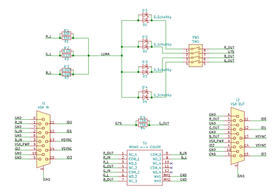
I have a tube from a Panasonic TR-990C that I'm using with the Compaq analog board. The analog board and yoke is the ONLY part of the Compaq Portable II being used; likewise the tube is the ONLY part of the Panasonic security monitor that I'm using. I will be using a small circuit consisting of diodes and resistors, described in a previous post (scroll up for that plzkthx), to combine the R/G/B signals off the motherboard into the mono 'video' signal required by the Compaq analog board. The motherboard is from a Wyse C-class (aka Wyse Cx0-series) thin client and I am extremely familiar with that system and its internals. It has a VIA Eden CPU and a DDR2 RAM slot for a single stick of laptop RAM. My particular example has an internal WiFi card that runs off an internal USB port on a proprietary 6pin connector. Drives operate off a 44pin IDE header, and I have a 16gb mSATA drive with an adapter to 44pin IDE that I will be using with the system.

I'll be installing Xubuntu 18.04 -- this is a 32bit system with a 32bit CPU, and as such Xubuntu 18.04 is the last version of that OS to support 32bit operation. It also is the first since Xubuntu 12.04 to properly support the chipset graphics, as a bug was introduced in an older version of the 'openchrome' video driver -- basically, the devs were burnt out and did not properly audit some incoming code, which broke support for its rarely-used VIA VX855 chipset as well as several other, somewhat more popular VIA chipsets with an internal structure. This was resolved in 'openchrome' bug #91966 and I am the person who filed that bug report. It took, annoyingly (at least to me) multiple *years* for the revised version of the driver to filter down through the various Debian-based distros -- and as a result, the various 'flavors' of Ubuntu 18.04 LTS are the only such editions of that distro to support the system properly -- by Ubuntu 20.04 LTS, 32bit support had been deprecated and was no longer extant, and all other versions of Ubuntu, beginning with Ubuntu 12.10, packaged the buggy 0.3.3 revision of the 'openchrome' driver.

All of this will be packed into the housing for a "Standard Technologies" brand 9in VGA CRT monitor. *That* monitor's original tube was damaged in opening the housing, and its electronics are elsewhere. The neck board for the tube, in the original design of that monitor, sits with its bottom edge against a 'shelf' in the back of the housing that's atop the recess for the cable exit. (Both power and data cables are hardwired in that design.) It is nearly impossible to open the housing, as a result, without shearing the sealant nipple off the back of the tube... hence all the crazy tube-swapping. The original idea was to upgrade the driver electronics and tube both in the Compaq; alas, the security monitor tube was not physically compatible -- the mount tabs are all wrong -- and the tube from the VGA monitor was quite predictably ruined when I opened the case. (It's in my eWaste bin and has a hole where the nipple used to be, having been sheared off per description.) At least the Compaq's analog board uses a much smaller neck board!

Thus what I'm trying to do is essentially find a use for what are now spare parts. I'm able to mock up the build as described, as I have another Cx0-series motherboard that unfortunately got knocked about enough to induce component-level damage and it no longer boots. It's fine as a placeholder, though.

Theoretically, I could use the original yoke and driver board from the security monitor, but I'm pretty sure I don't want to do that. It's a single-sided PCB but it absolutely will NOT fit the case intact, and it uses a linear power supply system spread throughout the board, as best I can tell, and the connector for the transformer is very, very strange to me and not at all low-profile. I would literally have to cut the board in at least thirds, bodge-wire the traces back together, and hardwire that transformer after removing the connector or at least cutting its pins flush. I'm arguably capable of the task, but I'm not sure it's one I'd want to take on, especially because I'm also not sure I could actually fit it into the case even in pieces like that. I'd also have to make sure the neck board wasn't dangerously close to the housing as per the original design, and find space for a VGA-to-composite scan converter PCB, which I'm not thrilled about; this is very much close-quarters combat as it is!

That said, when all's done, I'll have a tiny retro all-in-one that can run LibreOffice. That's actually the reason for the 800x600 minimum resolution -- it supports netbook displays that are 600px tall, but only grudgingly, and absolutely for sure LibreOffice will not support anything lower-resolution. (I posted in that particular bug report thread, but I am not the original filer and I don't remember the tracking number, either. Sorry.)

Reply 17 of 31, by mkarcher

User metadata
Rank l33t
Rank
l33t

The security monitor analog board won't be a better match than the Compaq analog board, as the security monitor analog board is meant for 15 kHz only which is even worse than the 15/18kHz Compaq analog board. So there is no need to try to bodge this into the 9" VGA monitor case.

What you should be able to do with Linux, though, is to generate a 700-line interlaced mode at 18.4kHz horizontal scan rate, and feed that into the Compaq analog board. It should be able to perfectly sync on it, as it basically equals the 350-line MDA mode it is designed for. To get square pixels, you could calculate a modeline for 960 x 720 interlaced (720 lines should be in tunable to fit the display using the vertical size control), if this mode doesn't exceed the low limit of the dot clock of your system.

Reply 18 of 31, by starhawk

User metadata
Rank Newbie
Rank
Newbie

I've actually tested the security monitor analog board and it is known good at SVGA resolution.

I don't know how to calculate modelines, but I vaguely remember how to feed them into xrandr. (I miss the days of xorg[dot]conf... what can I say, I used to use Puppy Linux 🤣.) If you can tell me how, though, I'll give the calculations a shot. The sort of thing you describe (essentially scan doubling) is exactly the sort of trick I was hoping for 😉

Reply 19 of 31, by mkarcher

User metadata
Rank l33t
Rank
l33t

MDA has 720 pixels at a pixel clock of 16.257 MHz, which means the active part of a scanline takes 44.29µs. The horizontal scan rate is 18.43kHz, so the complete line takes 54.26µs.
I suggested (to get a nice number of pixels) to squash 960 pixels into the 44.29µs. Thise requires a pixel clock of 21.67MHz. The total line takes 1176 pixels. That's not a "good" number as many graphics cards require the pixel count to be divisible by 8 (some even require 16). So let's pick 1168 pixels total, and re-adjust the pixel clock to obtain 54.26µs. This yields a target pixel clock of 21.53 MHz.

The horizontal sync pulse should start 16 MDA pixels after the last visible pixel. As our pixels are faster, we use 24 pixels "front porch" (time between the last pixel and sync start) and also 24 pixels "back porch". This yields these horizontal timings:

  • Pixel clock: 21.53 MHz
  • Displayed pixels: 960
  • Sync start at: 984
  • Sync end at: 1144
  • Total pixels: 1168

We can nearly clone the vertical timing from the MDA card: 370 lines, with 350 displayed, vertical sync directly after the last line. If we increase the displayed lines to 360, we shift the image upwards by 10 scanlines, but that should be adjustable with a pot. An interlaced mode requires an odd number of total displayed lines, so the total line count will be 2*370 + 1.

  • Displayed scan lines: 720
  • Sync starts at scan line 722
  • Sync stays on till 740
  • Total 741

This yields this modeline

Modeline "960x720" 21.53  960 984 1144 1168  720 722 740 741 interlace +HSync -VSync