As far as I remember I used the motherboard's regulator not the PSU one's and it got really hot. 🔥
It was only for those benchmarks here and between every run I let the system cool down. I'm not going to use a Radeon 8500 as default graphics card in this machine. That would be waste graphics power. The final graphics card is going to be a Matrox G400 Max.
Is the LX8383A-00CP still available. I would like to keep a spare part after that torture.
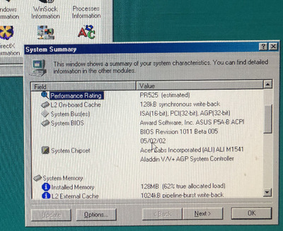
I dug out my P5A Rev. 1.06 yesterday primarily to make the "K6-III+ mod". But before that I did some tests. After upgrading to the latest BIOS I tested several FSB <-> multiplier combinations.
With FSB=100 everything seemed to be fine but the system wouldn´t start sometimes unless I "overvolted" the CPU by 0.1 or 0.2V.
Then I tried FSB=105 and 110 MHz with lower multipliers. The system would hang when DOS while loaded or start loading and show corrupted charakters. Overvolting didn´t make any difference. Sometimes the system would boot up with L2 cache disabled though. My first guess was the SRAM chip just wasn´t fast enough.
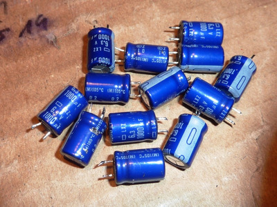
Then I thought of the instabilities Sphere478 observed here. Taking a closer look I noticed that my 1.06 had the same "Nippon Chemicon LXZ" electrolytics while in most cases ASUS used Rubycon and Sanyo caps on these boards.
I removed all of the LXZ - they are looking perfect btw - and measured capacity and ESR. While the capacity was still in the tolerance range and showed around 850 - 900µF, ESRs had values between 1 and 8 Ohms.
Having in mind that higher ESRs are deadly when dealing with low core voltages like 2V I came to the conclusion that this could be the reason for instabilities.
Using another PSU - no matter how powerful - would not help here at all since core voltage and 3.5V for memory and chipset are generated with the onboard voltage regulators alone.
Then I recapped the whole thing with "Rubycon ZLS" 1000µF 10V (ESR = 0.1 Ohm) and cleaned everything carefully.
Then I ran the tests again and there are no more instabilities! FSB 105 and 110 are running flawlessly now, a K6-III+ 450 is running at 578 MHz (105 x 5.5) without any problems.
Capacitors of the LXZ series are not known as "Badcaps" but I think they are just not good enough for this purpose, or they have aged...
majestykwrote on 2022-01-11, 16:44:I dug out my P5A Rev. 1.06 yesterday primarily to make the "K6-III+ mod". But before that I did some tests. After upgrading to t […] Show full quote
I dug out my P5A Rev. 1.06 yesterday primarily to make the "K6-III+ mod". But before that I did some tests. After upgrading to the latest BIOS I tested several FSB <-> multiplier combinations.
With FSB=100 everything seemed to be fine but the system wouldn´t start sometimes unless I "overvolted" the CPU by 0.1 or 0.2V.
Then I tried FSB=105 and 110 MHz with lower multipliers. The system would hang when DOS while loaded or start loading and show corrupted charakters. Overvolting didn´t make any difference. Sometimes the system would boot up with L2 cache disabled though. My first guess was the SRAM chip just wasn´t fast enough.
Then I thought of the instabilities Sphere478 observed here. Taking a closer look I noticed that my 1.06 had the same "Nippon Chemicon LXZ" electrolytics while in most cases ASUS used Rubycon and Sanyo caps on these boards.
I removed all of the LXZ - they are looking perfect btw - and measured capacity and ESR. While the capacity was still in the tolerance range and showed around 850 - 900µF, ESRs had values between 1 and 8 Ohms.
NC_LXZ.JPG
Having in mind that higher ESRs are deadly when dealing with low core voltages like 2V I came to the conclusion that this could be the reason for instabilities.
Using another PSU - no matter how powerful - would not help here at all since core voltage and 3.5V for memory and chipset are generated with the onboard voltage regulators alone.
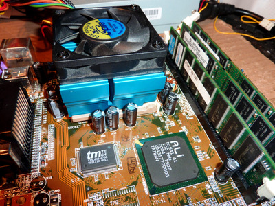
Then I recapped the whole thing with "Rubycon ZLS" 1000µF 10V (ESR = 0.1 Ohm) and cleaned everything carefully.
P5A_106_recap.JPG
Then I ran the tests again and there are no more instabilities! FSB 105 and 110 are running flawlessly now, a K6-III+ 450 is running at 578 MHz (105 x 5.5) without any problems.
Capacitors of the LXZ series are not known as "Badcaps" but I think they are just not good enough for this purpose, or they have aged...
Is there like a capacitor assortment kit that I can order or something for recapping motherboards?
Sucks every time I get a new board to have to make a new list and order all of those specific ones 🤣.
Maybe I should just have a tackle box at the ready 🤣
What are the best caps to use for motherboards? The ones you used?
In this case the list is a piece of cake: "13 x 1000µF 6.3V".
I preferred to use the 10V vetsion here, because higher voltages generally mean lower ESR. Rubycon ZLS or ZLH are a perfect choice for this application. Of course there are adequate Panasonic or Nichicon types also.
The form factor of the original caps is 8mm x 12mm. The ones I used are 16mm high but this isn´t a problem here.
When it comes to electrolytics there are certain physical limits. It´s very hard, if not impossible to produce a 1000µF 6.3V or 10V capacitor (AL-electrolytic) in an 8mm x 12mm csase and at the same time have low tolerance (like +-20%), a very low ESR plus a long lifetime (like 5000h - 10.00h). You need a bigger case for this OR you have to sacrifice one (ore more) of the goals.
Early failure as a result of rising ESR and diminishing capacity is guaranteed in this case..
I just had an idea.
We need a motherboard recap mouser project thread.
People with motherboards post mouser projects with all the needed caps, just click order and good to go!
Then I thought of the instabilities Sphere478 observed here. Taking a closer look I noticed that my 1.06 had the same "Nippon Chemicon LXZ" electrolytics while in most cases ASUS used Rubycon and Sanyo caps on these boards.
I removed all of the LXZ - they are looking perfect btw - and measured capacity and ESR. While the capacity was still in the tolerance range and showed around 850 - 900µF, ESRs had values between 1 and 8 Ohms.
Wow, I am surprised LXZ did not hold up after 20 years -- I'm not being facetious... 8 Ohms is unacceptable.
I am slowly losing faith in the long-life non-aqueous series from Japanese manufacturers (Panasonic FC, Nichicon PW, and now UCC LXZ).
I was surprised and disappointed also.
In most cases decreasing capacity occurs together with rising ESR. - especially when the caps dry out due to rising temperature.
Here capacity was still good.
Then there are cases when capacitors are poorly produced or the nominal electrical parameters are so far exaggerated that they fail in regular operation.
And there are cases when mainboard / PSU vendors use capacitors out of specs, at too high temperatures of the environment, higher ripple currents than specified or very close to the nominal voltage. I would suspect the ripple current here that is highly dependant of frequency and form factor (surface area). Designers / layouters have made countless mistakes in this field.
This 'could' be the case here and explain why LXZs were ageing too fast.
This 'could' be the case here and explain why LXZs were ageing too fast.
Either that or perhaps cascade failure (PSU caps were no good, and it passed more ripple to the on-board caps than they were rated to handle)... I still prefer LXZ over PW or FC (FC should not be used at all, they all have a manufacturing defect), because I've not heard of any other cases other than yours of them failing yet...
It's also worth noting that the overwhelming majority of P5A boards use Rubycon YXG (Asus used these almost exclusively in that era)... YXG is an aqueous series, and they do in fact hold up very well over time, but I personally do swap them out on old Asus boards when I see them... I don't mind 20 years on a non-aqueous cap, but I feel 10-15 years should be the maximum for an aqueous series.
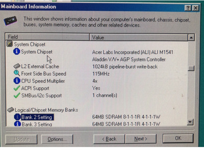
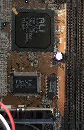
I bought one of the 1.06 versions of this board which has the ALI M1541 rev. G northbridge and no tag chip. If I wanted to upgrade the cache from 512kb to 1mb, would I need to add a tag chip or can the integrated chip already support this?
According to this thread, I can already cache up to 512MB. But if I wanted to upgrade the cache, I still don't know if the northbridge would support it.
Has anyone seen a 1MB cache chip with a rev. G northbridge without a tag clip present?
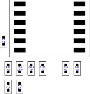
Did anyone successfully upgrade their cache to 1MB? I have a Rev. 1.06 (without external Tag) that I'd like to upgrade. From what I could gather the Tag and surrounding components should look something like this:
I did the upgrade of 1.06 P5A recently using an image from Skalabala. Just put 33 ohms instead of 0 ohms and 0.22 uF instead of 0.1u for tag. The tag IC was pulled from SIS 530 SS7 mobo. I’m waiting now for the solid-state caps to replace all the electrolytes. The 4n cache was purchased from AliExpress. Gonna do the same for P5A-B mobo and report here. I have a donor for rev G northbridge.
Just successfully swapped 512k 5ns cache in Asus P5A-B rev 1.04 with 4ns 1Mb module. Runs at 100 MHz, 105 unstable . 110 and above is unable to boot at all. I’m sure it’s the TAG SRAM, because 512k behaved similarly. I also have Rev G north bridge to swap a stock rev E 1542 chip if I won’t get it stable. SuperPi fails to run at 550 with K6-2+ by now. But , 3Dmark2000 runs and I got 1700 points with GF2MX PCI.
You've got balls of steel to feel comfortable swapping out your northbridge.
We've got balls of lead ))
Well, we have positive experience with south bridge A1-> B1 in “K6 aimin for stats” thread. The mobo was recovered from metal scrap. Both of them. The donor is Acorp 5ali61.