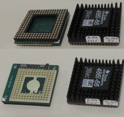
The Cyrix chips have 1 KB L1 cache, the TI have 8 KB.
Can't comment on performance, as I have yet to test them, but I believe the TI will outperform the Cyrix, if only because of the extra cache. Someone else will probably know more.
See my graphics card database at www.gpuzoo.com
Constantly being worked on. Feel free to message me with any corrections or details of cards you would like me to research and add.
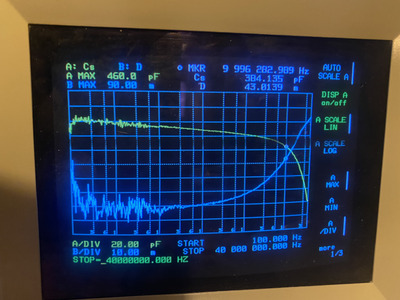
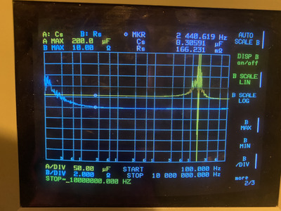
Buddy and I did a little testing with some 0603 capacitors today
Conclusion, what we can try to target 80mhz and 5khz is to populate the 3.3v pga pin pads with alternating 470pf and 10uf alternating on between half, to all the pga pin cap points.
We should also try to use capacitors using mpo or c0g dielectric.
I need to read back in the thread and see if we have checked to see if this is common mode noise or not. If so then there is no point in trying to filter that. To test for common mode noise connect ground lead together with sense lead and connect to vcc3.
Gotta run. Making notes so I don’t forget.
My unit isn’t yet running to take my own unit readings yet. Still waiting on some parts to show up.
Btw, apparently adding a ferrite ring to the test lead wire can help filter common mode noise.
Here are pics of some of the caps tested. Not all. Interesting data. I believe the datasheets often have this but it is nice to see it in the flesh.
I've been meaning to update this thread but haven't been able to find the time. Trying to keep up with PM's and other threads is becoming very challenging for me. From before,
NOISE TARGETS TO BEAT FROM ALPHA1 - 1x mode only - LP38503TS-ADJ
Vout
5 KHz : Vpp = 82 mV (no change)
80 MHz : Vpp = 40 mV (no change) central region's 1210-sized Cin caps have no effect on Vout
Vin
5 KHz : Vpp = 60 mV (increased noise by 5 mV) Vin noise increased by only 5 mV after removing central Cin caps.
Alpha 2 - round 8 Now comparing with MIC29302WT regulator to see if central Cin caps help in any way
Cin = 10 uF cer
Cout = 22 uF tant
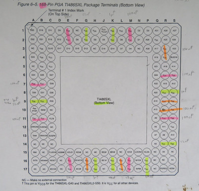
PGA-168 pins, add Cout = 10x 100 nF, 4x 1 uF, 4x 22 nF
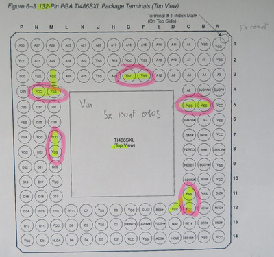
PGA-132 pins, add Cin = 5x 100 nF
Vout
5 KHz : Vpp = 86 mV with or without central Cin
80 MHz : Vpp = 34 mV with or without central Cin
Vin
5 KHz : Vpp = 54 mV with Cin central caps and 62 mV without Cin central caps.
The conclusion from this round of testing was that adding 7 Cin central MLCC capacitors does not help Vout at all and helps Vin by only 5-8 mV. Cout central caps had been removed from Alpha2's design, thus determining their benefit, if any, was not measured.
Alpha 2 - round 9
Assembled a second w/MIC29302WT regulator, but with only 100 nF caps.
Cin = 10 uF cer
Cout = 22 uF tant
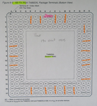
PGA-168 pins, add Cout = 18x 100 nF
PGA-132 pins, add Cin = 5x 100 nF
Vout
5 KHz : Vpp = 84 - 94 mV
Vin
5 KHz : Vpp = 50 mV
Conclusion, the MIC29302WT regulator showed similar noise characteristics to that of the LP38501TS-ADJ. The LP maybe demonstrated every so slightly less Vout noise, but this is within measurement error. The maximum output voltage from the MIC regulator under full load was 4.81 V, while it was 4.92 V for the LP regulator. The central region's Cin caps do not reduce Vout and only reduce Vin by an inconsequential 5 mV.
By way of comparison, I remeasured the Improve-It + Gainbery interposer's noise with the SXL2, and noted,
Vout
5 KHz : Vpp = 180 mV
80 MHz : Vpp = 96 mV
Vin
5 KHz : Vpp = 140 mV,
thus the Alpha units demonstrated improved noise characteristics. Ideally, we'd have noise values from the Powerleap unit to offer a fairer comparison. Note that we have not checked for noise and reflections on any of the other pins, like address, data, HLDA, etc. Since we having a working unit at 80 MHz already, I do not see any value in this.
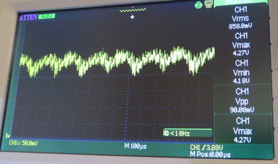
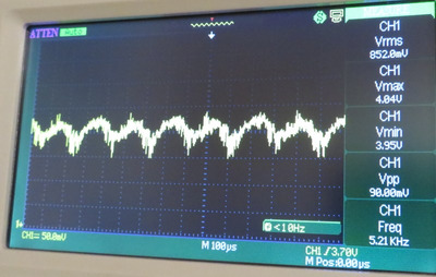
Here is a scope capture of the noise on the MIC29302WT:
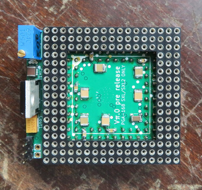
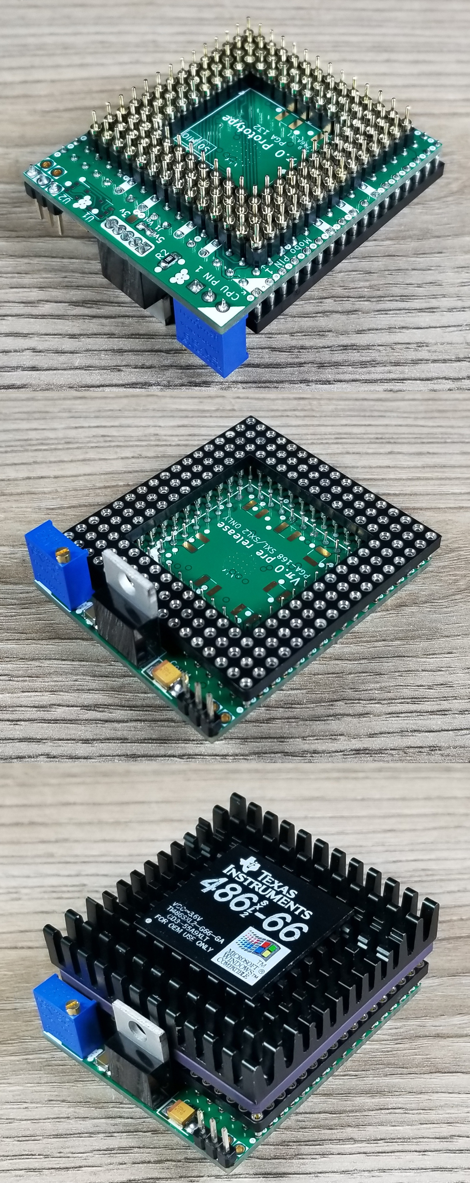
However, results with all 100 nF caps were just as good. This is what I have, overall, ended up with for PGA168 capacitors and locations. You will see some locations that are not utilised. I tried adding caps to these non-utilised regions, but it did not improve the noise response, and so these caps were removed. In general, having adjacent PGA168 caps do not help the noise response. You will notice that I added a cap to VCC5 on PGA168, mostly because I had some extra caps. Here is the final layout, but I think using only 8x caps is more than sufficient:
Here are the caps I placed on the PGA132 pins to serve as Cin. There are only 5 locations which are convenient for soldering. It is more than sufficient. Central core caps not needed.
I am not sure what JLCPCB changed to cut costs on their $2 6-layer boards (Alpha2), but my general impression was that the build quality on the non-cost-reduced boards at $85 (Alpha1) were a little better.
FINAL NOISE of Alpha2 w/LP38501TS-ADJ
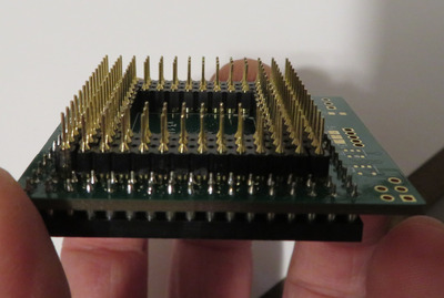
There had been some comments on pin alignment concerns. Here is a photo of the pins lined up. Generally, during assembly, you want to have the pins in a spare PGA132 socket to keep them straight. You may also need to lightly sand the ABS between the pin rows and ends to make for a nice fit.
While you could use 0603 capacitors and place them down onto the PCB, for ease of soldering, I would just take 0805 caps and press them into the PGA168 pins, just far enough to hold them in place and solder.
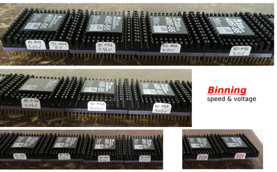
Next on the agenda was binning. I have 13 SXL2-66 CPUs.
It took quite some time to determine the maximum frequency at which voltage for all the CPUs. Of the 13 CPUs, only 2 wouldn't run reliably at 80 MHz. The other 11 ran at 80 MHz, but voltage was important. The results are shown in the image, but I will provide them here as well.
CPU-1
Max freq: 75 MHz
Min voltage required: 4.15 V
CPU-2
Max freq: 75 MHz
Min voltage required: 3.65 V
CPU-3
Max freq: 80 MHz
Min voltage required: 4.20 V
CPU-4
Max freq: 80 MHz
Min voltage required: 4.15 V
CPU-5
Max freq: 80 MHz
Min voltage required: 4.10 V
CPU-6
Max freq: 80 MHz
Min voltage required: 4.10 V
CPU-7
Max freq: 80 MHz
Min voltage required: 4.05 V
CPU-8
Max freq: 80 MHz
Min voltage required: 4.05 V
CPU-9
Max freq: 80 MHz
Min voltage required: 4.05 V
CPU-10
Max freq: 80 MHz
Min voltage required: 4.0 V
CPU-11
Max freq: 80 MHz
Min voltage required: 4.0 V
CPU-12
Max freq: 80 MHz
Min voltage required: 3.95 V
CPU-13
Max freq: 80 MHz
Min voltage required: 3.85 V
Max freq: 90 MHz
Min voltage required: 5.0 V
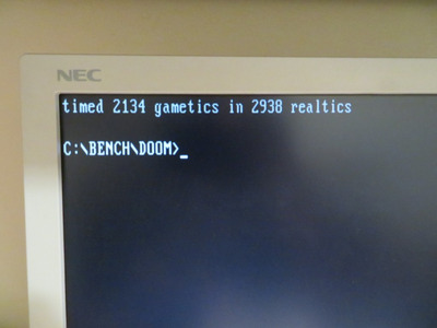
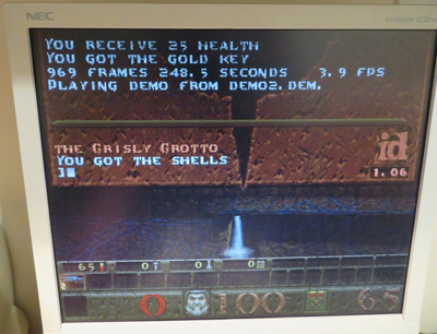
My testing criteria was to run the DOOM and QUAKE timedemos to completion, then let Quake run in a loop for 30 minutes. Reboot, then load Windows 3.11, open IE5 and load a google search result.
Plan your life wisely, you'll be dead before you know it.
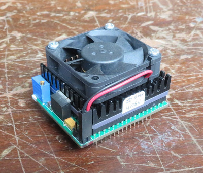
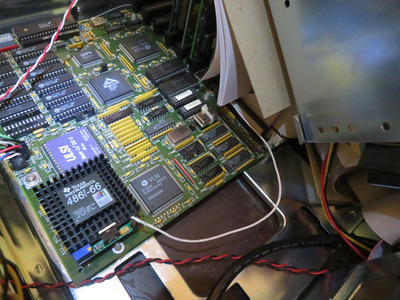
To achieve 90 MHz on just one of my CPUs, I needed to provide 5 V, however, even with the LP38501TS-ADJ regulator, the maximum I could output was 4.92 V under full load. At this voltage, the CPU was only quasi-stable at 90 MHz, meaning, it couldn't always complete the test criteria. To run it at 5 V, it should be possible to remove the regulator and short Vin with Vout. Alternately, with LP38501TS-ADJ, pin 1 is the enable pin. Perhaps it would also be possible to disconnect pin 1, leave the VRM in place, and short Vin to Vout. In any case, I didn't want to remove the regulator, so I merely used my Improve-It SXL interposer, which runs at 5 V and has no VRM on board. Improve-It interposer shown here:
I haven't yet decided how to proceed with running the SXL2 at 90 MHz. I do plan on making a system out of the SXL2, but with only one chip that can do 90 MHz, I would likely limit the setup to 80 MHz. Alternately, I was thinking I could get a fairly weak peltier pad, like a TEC1-12702 (2 A at 12 V) and run it at 5 V. This low voltage will hopefully prevent condensation and extended the life of the SXL2 CPU at 90 MHz. User pshipkov is the master of this and I may just step aside and let him experiment with this before I proceed further.
It would be preferred if I could procure another batch of SXL2 CPUs and bin them further, in hope of finding a sample that could do 90 MHz at a lower voltage, but with the costs adding up on my end, I think I'll leave this for someone else. To date, I'm in this project about $600 USD and am thinking it is time for me to close the bank.
Last I checked, JLCPCB re-added their $2 promo, so hopefully others will be able to assemble their own super 386's now.
Plan your life wisely, you'll be dead before you know it.
Might be best to settle for 80 mhz if you are running low on motivation/funds, or continue binning if you find more motivation 😀. Maybe you can sell the 80 mhz samples you have online as 80mhz vetted chips for some extra funds. Possible people might like to buy them knowing they will at least be able to get 80 mhz.
I think with a reasonably (not unreasonably) large enough sample size that 90 mhz chip might be findable based on what I have seen in other binning operations.
You might even be able to offer one of the online sellers a service of binning their supply in exchange for a few well performing samples. Maybe they will take you up on it?
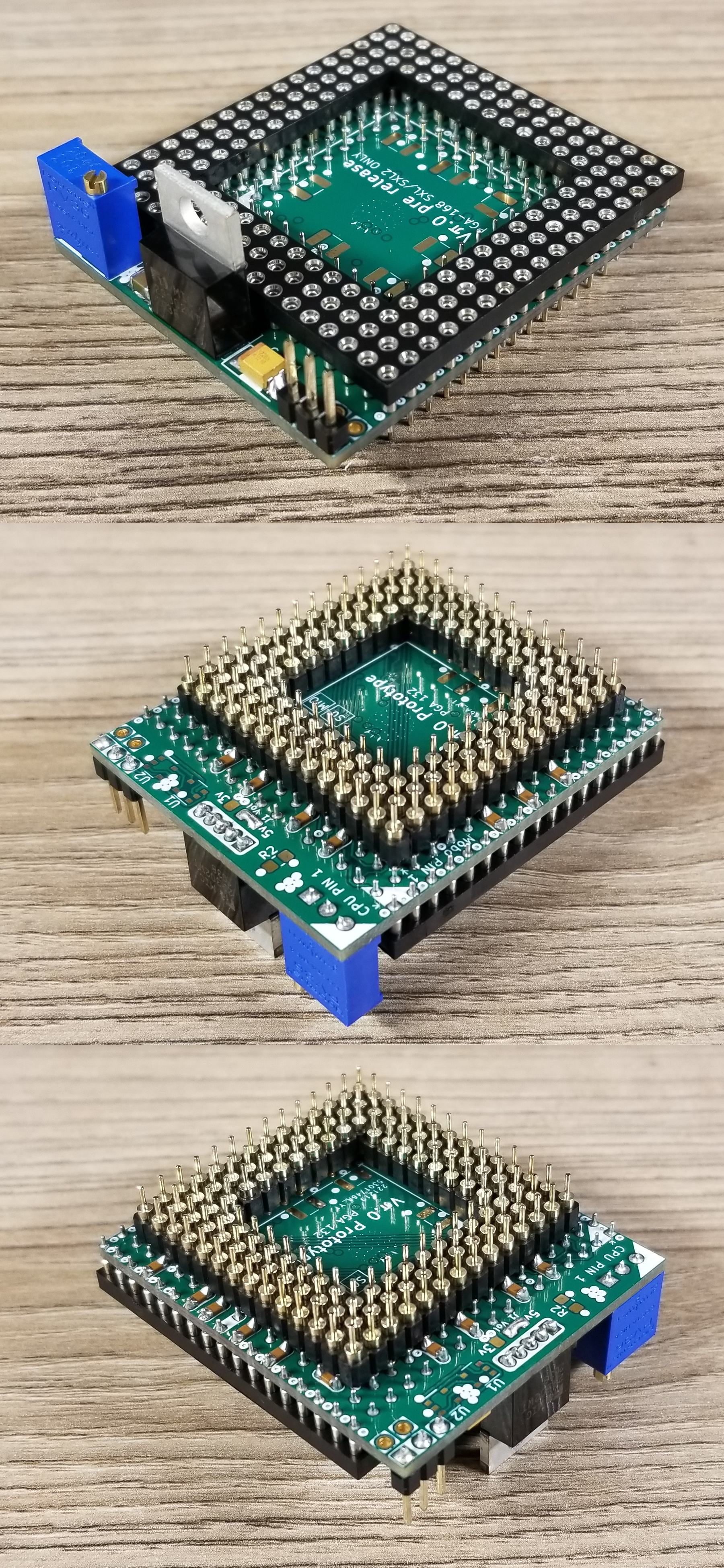
Got two interposers in place.
Didn't solder the array of capacitors - not convinced yet they are real factor on operational level.
Will add them later to one of the interposers and compare outcome against the other.
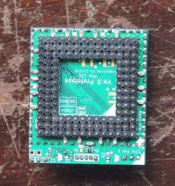
Don't turn your unit on with the CPU in that orientation. You need to rotate the CPU 180 degrees, otherwise you will be sorry.
I noticed you went for a physically smaller Cout capacitor. I little tight on pad spacing, but may look more symmetric to that of the adjacent 1210 ceramic.
At minimum, I'd suggest 8x 100 nF 0805 caps on the PGA168 pins. Otherwise, you'll have nearly half a volt of noise on VCC3. If you don't care for adding caps to the PGA pins, you can add 1210 caps to Alpha1 in the central region. However, I am looking forward to your performance results of no caps vs. 8x caps. With 430 mV of noise, I suspect it might matter at the higher frequencies on some motherboards. We'll see...
Plan your life wisely, you'll be dead before you know it.
err fixed the image.
thanks for pointing out.
i simply placed the cpu on top of the adapter for quick photo.
it will be couple of days before i test the adapters. dont want to do a sloppy first test inbetween other stuff - this is how damaged components happen.
pshipkovwrote on 2023-03-15, 23:20:Got two interposers in place.
Didn't solder the array of capacitors - not convinced yet they are real factor on operational leve […] Show full quote
Got two interposers in place.
Didn't solder the array of capacitors - not convinced yet they are real factor on operational level.
Will add them later to one of the interposers and compare outcome against the other.
This is how things look so far:
VERY nice soldering job!
Please use the "quote" option if asking questions to what I write - it will really up the chances of me noticing 😀
Thanks Henrik.
The second adapter turned even better. Still few elements missing. Hope i dont mess up.
I developed my own technique for precise soldering. Works well.
Very thin hotend and a thin solder wire.
Put flux on the area for soldering.
Touch gently with the tip of the hotend and while the flux is sizzling touch with the solder wire the hotend 1-2 mm above its end where it contacts the area for soldering.
The hot metal instantly slides down and settles in just right without leaving crust around the through hole or whatever is being soldered.
Angle of the soldering iron is important. 45 degrees works best most of the time.
Once the soldering is over there is only soft flux leftover that gets removed very easily with toothbrush under warm streaming water.
Btw, 90mhz is quite within the range of these sxl2-66 chips.
They light up even at hundred, but i dont have great feeling about stable 100mhz.
Last edited by pshipkov on 2023-03-21, 14:10. Edited 1 time in total.
When you say "tin", I am guessing you mean "thin"?
I'll have to try soldering this one day. I don't normally like to rely on flux due to the extra time it takes, clean-up, and short shelf-life. Which flux tubes are you using? I have SMD291.
Plan your life wisely, you'll be dead before you know it.
I am finding the SXL2 Alpha 1/2 units are functional at 66 Mhz on this motherboard, but they do not play well with my clock doubled ULSI DX2-66 Co-Pro. Quake will get hang-ups, "page error", or some other garbled polygons after about 20 seconds of playback. If the polygon distortion doesn't persist for more than 1-2 seconds, Quake will continue playing; but if any longer, Quake will kick you out with a page error.
If I use a non-clock-doubled ULSI Co-Pro, the above issue does not occur. However, if I use a Cyrix FasMath, Landmark Speed Test shows nothing for the FPU. If I put the Evergreen QFP SXL2-66 back onto the motherboard and no issue with the Co-Pro. The exception was that when using a FasMath, the Landmark FPU score would start out high, around 200, then slowly drop over the course of a minute or two, to around 145. Very odd behaviour. No issue with ULSI Co-Pro though.
I did not witness this fussy FPU dependency on the other motherboards I tested with Alpha 1/2. I had hoped to start using an Alpha1 or 2 unit in my AMI board, but I guess this won't be happening. With only a handful of the Evergreen SXL2-66 units remaining, I wanted to store it safely away.
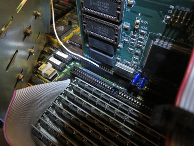
I did manage to test out the MEMW# function for flushing the L1 cache. See below:
This feature is functioning as expected and is needed if going to use the flush method to clear the cache. If you have an older 386 board and try to enable the flush pin without the MEMW# connection, the system will hang up. However, when I compared DOOM results using BARB and later FLUSH, I did not observe any performance difference. When I tested this difference on some other boards in the past, I did notice a small performance difference between BARB and FLUSH.
Ideally, we'd have a small ISA card to plug the MEMW# unit into, but I found you can take a 22 gauge wire and stuff it into a used ISA slot, like that shown above.
Plan your life wisely, you'll be dead before you know it.
Landmark FPU score would start out high, around 200, then slowly drop over the course of a minute or two, to around 145.
I've seen that on 386DX CPUs as well. I have a mobo that scores a tad bit higher in floating point than other ones, but it's very picky about CPU and NPU pairing. Even hangs with some. Add some active cooling over the chipset (a fan nearby blowing some air should be good enough) and see if that makes the drop less obvious. I suspect the chipset timings are a bit on the optimistic side of things and only chips that meet them with some margin work properly.
I did manage to test out the MEMW# function for flushing the L1 cache. (...) However, when I compared DOOM results using BARB and later FLUSH, I did not observe any performance difference.
The internal cache in these CPUs is tiny, AFAIR it doesn't even provide 90% hit ratio, and also is just 2-way and shared between data and code. I'm pretty sure there's a lot of cache trashing going on in games like Doom that have rather big dynamic data (and code) requirement. Also, MEMW# method is not really all that superior to BARB - because you don't know if the write was going to ISA or main memory. Yes, DMA write to ISA memory is rare, but might happen in some systems. A better way would be to intercept /WE to SIMM sticks, but since there are usually 4 of those (or even 8 in some banked schemes) you need additional, fast gate for that.
Were you running Doom tests with sound though? Typical SB-type way to play back digitized sound is via DMA, pretty frequently, this causes a lot of flushes when using BARB. Well, the small cache is probably trashed anyway but there is a performance penalty for activating a cache flush, whatever state it's in. So with SB sound playback you should see improvement with MEMW# over BARB.
Deunan, that is a good point - I didn't run DOOM with sound for this quick test. In the past, I'm pretty sure I had sound enabled when comparing BARB with FLUSH, but the performance difference was very small, on the order of 15 realtics, if I recall right. I've put the system away for now, but next time I have it out, I'll try to fan the chipset.
Plan your life wisely, you'll be dead before you know it.
Completed the second adapter.
This one with bunch of capacitors.
Will compare soon the two and share noise levels and if there is a difference in overclockability (tm).
Were you also planning to add the PGA capacitor pins to the top as well?
I noticed that you mounted your male-male PGA pins opposite to mine. I am curious, what was your rational behind this? The reason I mounted my pins in the orientation shown in my images was because of the pin length, pin width, and ability to use a CPU removal tool.
The end of the PGA header with the wide pin base is too wide for a PGA CPU removal tool to be used. The side with wide base is also shorter (3 mm) than the longer side (4 mm). I find that 3 mm is just barely long enough to click into the motherboard's socket and maybe this will limit your lateral contact area, or make the CPU more prone to fall out on a side mount. The other reason was the width of the pin on the wide base end, which is 0.58 mm , compared to 0.45 mm on the long side. If you measure a standard Intel i486SX or Am386DX pin width, they are 0.43 mm wide. So in using the wide side of the PGA header for socket mating (0.58 mm), you may stretch out your motherboard's PGA132 sockets.
These were all the issues I considered when selecting the side to use. Since you used it in the opposite direction, I am wondering if I overlooked something more important? If so, could you let me know?
Last edited by feipoa on 2023-03-22, 07:31. Edited 1 time in total.
Plan your life wisely, you'll be dead before you know it.
Not sure what you mean by “add the pga pins to the top”.
The pga132 pins are oriented that way on most adapters i have seen.
I dont have cpu removal tools, so your notes a bit ambiguous. But i think i understand what you mean.
Also, if the pins are oriented that way, insertion and removal is much easier, yet the adapter sits firmly in the socket when inserted.
Btw, where you measure for noise levels ? Can you confirm, so i do the same here for conformity.
Last note - silk screen on these PCBs can easily crack and chip away.
It requires precise and gentle handling.