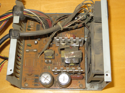
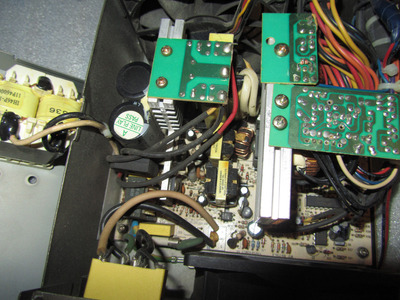
Eh, I'm starting to think some people posting about "crap PSUs" haven't actually seen a low quality PSU. This is what the bottom of the barrel looks like:
And yet it works, even in this state, so I'll probably end up using it for less important projects, of which I have many.
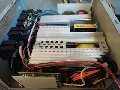
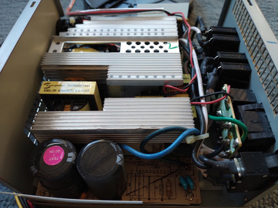
BTW, the size or weight of the heatsinks is not a good indicator of the quality. Well, not with the modern digital PSUs, these things are so efficient that there isn't any need for a lot of heat rejection surface. It does hold true for the AT era stuff though, and ATX up to a point. If you see massive heatsinks then ask yourself why are they needed, does the PSU high current output demand more cooling or is the design crap and inefficient. Or both. I had a pretty decent Tagan 570W modular PSU that worked for like 15 years with little downtime before if finally died - and it was heavy with massive heatsinks but that was also due to the rather poor ~70% efficiency. These days I wouldn't even touch a PSU rated below 80%, and my current PSU is 94% and thus I've yet to see it spin the fan (except in test mode). Which is great, no noise and no dust.
Anyway, back the the photo, this is supposedly 200W unit and the PCB is also marked as such, but frankly I'd be worried trying to pull 150W out of it. Should not be a major problem considering most ot the stuff I build tops at 50W or so (and more like 30W for 386). The two input capacitors are marked 330u/200V 105C but both are measuring about 220u so I suspect these were fakes from the factory (especially considering their size). There is no input filter, I've added a 0.1u X2 cap, might actually look for a used common mode choke later as well. Output caps are 220u for auxilary voltages and 1000u for main 5V and 12V. No pi filter for 5V rail, in fact the choke wasn't even in the design. I'll add some 100nF ceramic bypass caps for the new low-ESR electrolytics but frankly this is not a PSU I want to spend money on, so I won't be putting my best Panasonic or Nichicon caps in it.
Also, no fan speed control, though perhps that is a good thing looking at the minimalistic heatsinks. But again, it works, and it was "free" since it came with an AT case I got pretty cheap.