Reply 20 of 21, by Adriand1281
majestyk wrote on 2022-08-24, 15:16:We don´t know what´s connected to pin1 in some layer inbetween. Cutting visible traces might not be enough. You could also bend […]
We don´t know what´s connected to pin1 in some layer inbetween. Cutting visible traces might not be enough. You could also bend pin1 upwards so it won´t come near the landing on the PCB and make a wired connection to ground, if you want to use the fixed regulator version.
I would go with the adjustable version. If R2 is 200R (have you measured in both directions?) and 127R goes to Vout, you´re fine.
[(200/127) + 1] x 1.25 = 3.22V
You would keep the possibility to select different core voltages in the future if needed.
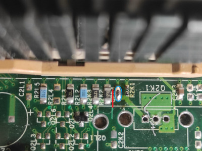
I am also of the opinion that the original version would be better, unfortunately I could not find this chip in the ADJ version in my country and the shipment from the USA to Europe will exceed the value of this motheboard. So far I cut the path, I made it in such a way that it will be easy to fix the connection if I manage to buy the chip. There is an open line between leg 1 of the system and all the tensions and ground so it can be considered a success. I will make a jumper to ground and as soon as I get the system we will see if it will work stably.