VOGONS


Reply 20 of 54, by rasz_pl

User metadata
Rank l33t
Rank
l33t
cyberluke wrote on 2022-08-18, 10:48:

So the issue is that the faulty joystics beeps with short circuit error and have infinite resistance.

-resistance measurement doesnt beep
-infinite resistance is the opposite of short circuit

cyberluke wrote on 2022-08-18, 10:48:

But it shows voltage change correctly.

is it one of those digital joysticks with actual electronics inside? open it up

cyberluke wrote on 2022-08-18, 10:48:

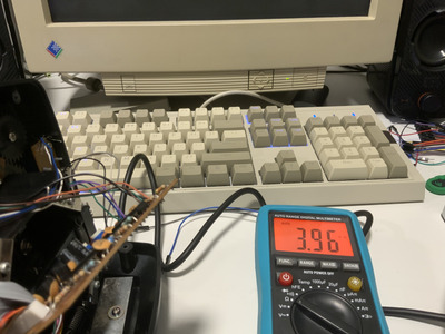
Quickshot center is 59.2kOhm...minimum is 5 Ohm. Maximum is 135k Ohm.

thats more like it, proper joystick 😀

cyberluke wrote on 2022-08-18, 10:48:

Measuring pin 1-3 (Joystick 1 X axis and +5V)

dont put any voltage on anything when measuring resistance, in this particular case it can only lead to bad measurements, but if you do this while checking motherboard or monitor you will fry something important

set multimeter on ohm range
put one lead of multimeter on pin 1
put second lead on pin 3

Open Source AT&T Globalyst/NCR/FIC 486-GAC-2 proprietary Cache Module reproduction

Reply 21 of 54, by cyberluke

User metadata
Rank Member
Rank
Member

Ah, sorry for that. The beep means short circuit. Okay, so I don't need to have powered +5V on my electronic breadboard, turned it off. Verified measurement on both joysticks...it still works 😁

It is this joystick: https://www.ebay-kleinanzeigen.de/s-anzeige/j … 720712-225-3353

It features auto-calibration. I believe it is digital, same as Sidewinder 3d. It emulates only CH Flightstick Pro or Thrustmaster FCS. So I would think that inside it is digital, but for emulating these two standards, it would output analog voltage (which it does).

Now without the power source, measuring resistance shows 10M Ohm and it does not change at all when moving the stick. But if you give +5V power and measure X axis together with ground, you will see it reacts and outputs a voltage change.

Reply 22 of 54, by rasz_pl

User metadata
Rank l33t
Rank
l33t
cyberluke wrote on 2022-08-18, 12:09:

It features auto-calibration. I believe it is digital

yep, that explains not being able to measure resistance 😀 it "emulates" potentiometers somewhat similar to how Commodore C64 1351 mouse emulated paddles.
Here is someone replicating this mouse with arduino https://c65gs.blogspot.com/2017/11/1351-mouse … acy-better.html
another one http://www.zimmers.net/anonftp/pub/cbm/docume … ouse/Mouse.html
C64 SID POT readout works similar to gameport 555 timers, waiting for capacitor to charge, except its a Lot better engineered with whole machinery hidden away in asic, and programmer reading nice 8bit auto refreshed registers without the need for slow manual pooling eating your performance like on PC.

cyberluke wrote on 2022-08-18, 12:09:

So I would think that inside it is digital, but for emulating these two standards, it would output analog voltage (which it does).

Its not really obvious, one can output analog voltage out of a DAC, pwm modulated signal, or even use real digital potentiometers.

cyberluke wrote on 2022-08-18, 12:09:

But if you give +5V power and measure X axis together with ground, you will see it reacts and outputs a voltage change.

do you have an oscilloscope? would be nice to look at that output, preferably while joystick is connected to real gameport and being constantly read, plus a look at 5V voltage going to the joystick.
possibilities I came up with without seeing inside the joystick:
- supplied 5v is not clean and somehow disturbs emulated output
- joystick has dried capacitors and experiences supply drops internally
- its some kind of compatibility edge case and nothing can be done

Open Source AT&T Globalyst/NCR/FIC 486-GAC-2 proprietary Cache Module reproduction

Reply 23 of 54, by cyberluke

User metadata
Rank Member
Rank
Member

Yes, I have small oscilloscope - 2 channels - OLED display - on breadboard. XMEGA Minilab: https://www.seeedstudio.com/XMEGA-Xprotolab-p … tailer_products

Manual is here: http://www.gabotronics.com/download/xscopes/x … opes-manual.pdf ...2 analog channels and 8 digital channels. I did not want to do it, but it seems I will have to open this brand new joystick. The screws are beneath the rubber stands.

I have more software experience, but I have a lot of hardware & electronics because I did run makerspace openlab near Ostrava.

Reply 25 of 54, by cyberluke

User metadata
Rank Member
Rank
Member

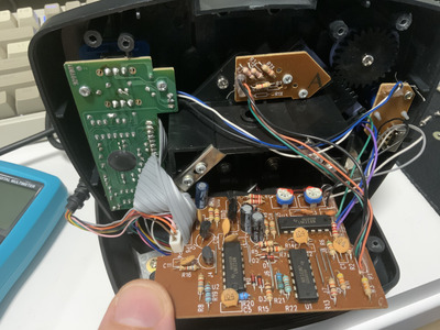
So this is what the board looks like. Visually it is new.

The green board on the right is only for turbo button switch.

This joystick emulates throttle and rudder (analog axis) with POV hat (digital like buttons). That is probably why there are resistors at the top for R2X, R3X, R2Y, R3Y and not for R1X, R1Y. I verified in Windows control panel that POW switch increases throttle and rudder axes digitally by one step increments. When holding it will continuously increase or decrease, but the step delay seems to be very long. Should be tweaked somehow later to make it useable - this is in TCS mode. In CH mode, the POV can be operated fully digitally and that feels better.

Next, the main board features two trimmers marked as VR1 and VR2. I guess that would mean variable resistance trimmer. This might be the actual solution.

The board on the right is mode switch between TCS and CH.

In the corner, there is black cog wheel for adjusting the mechanical range of the stick. Manual states that by decreasing the operational field of the stick, you can get faster response. So it means you perform smaller movement to output the min max values on the gameport.

Now I’m going to set up oscilloscope measurement.

Attachments

Reply 26 of 54, by rasz_pl

User metadata
Rank l33t
Rank
l33t
cyberluke wrote on 2022-08-18, 14:04:

The green board on the right is only for turbo button switch.

this is the whole brain of this joystick, sadly a COB blob

cyberluke wrote on 2022-08-18, 14:04:

Next, the main board features two trimmers marked as VR1 and VR2. I guess that would mean variable resistance trimmer. This might be the actual solution.

this is analog frontend, 3 opamps might be to condition signals from potentiometers before they go into the blob microcontroller, or they could be discrete ADCs.
Q1 Q2 Q101 Q102 might be what they used to pwm analog voltage ack to gameport. Its all speculation without reverse enginnering connections and diagram
VR1 and VR2 are very close to where main joystick potentiometers connect, wouldnt be surprised if they are just for trimming those and wont affect output quality

cyberluke wrote on 2022-08-18, 14:04:

In the corner, there is black cog wheel for adjusting the mechanical range of the stick. Manual states that by decreasing the operational field of the stick, you can get faster response. So it means you perform smaller movement to output the min max values on the gameport.

its connected to another potentiometer, you could spray some deoxit/wd40/isopropyl alcohol into all those potentiometers just in case

Open Source AT&T Globalyst/NCR/FIC 486-GAC-2 proprietary Cache Module reproduction

Reply 27 of 54, by cyberluke

User metadata
Rank Member
Rank
Member

Ok, I measured something interesting on oscilloscope. Uploading to Youtube. There is a Ramp signal and its length is getting smaller and smaller if you move the axis to the top. Then it stops.....video in 10 minutes.

Reply 29 of 54, by cyberluke

User metadata
Rank Member
Rank
Member

Could it be some issue in autocalibration on faster CPU?

I tried to re-measure resistance when connected to PC.

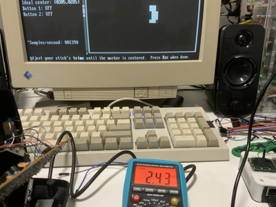
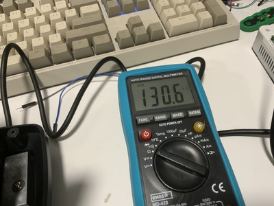
Without any software running, the middle position shows only 4k Ohm. Top position shows 130k Ohm.

When running calibration software with timer loop, resistance is 2M Ohm.

Is some component faulty or is it by design? Can it be fixed?

Attachments

Reply 30 of 54, by cyberluke

User metadata
Rank Member
Rank
Member

The issue is that when I move the stick:
- lowest position, lowest resistance = 3k Ohm
- middle = 4k Ohm
- top = 130k Ohm

Clearly the autocalibration is not correct. The middle should be 50-60k Ohm

Reply 31 of 54, by rasz_pl

User metadata
Rank l33t
Rank
l33t

Everything looks as it should. Ramp is there because capacitor is slowly being charged.
At the 'down' position its charged very slowly (in conventional joystick this would be high resistance close to 100kohm), at 'up' its faster so the ramp gets shorter (low resistance). Surprisingly you seem to have trouble here?? This is weird as most joystick troubles were in the 'down'/high resistance case caused by fast cpu leading to overflow in measurement routine - its too fast and runs out of counter before capacitor is fully charged.

but here, here somehow charging the capacitor too fast leads to error condition? I dont even understand how would that happen ???

btw that fast/slow switch on the gameport card switches the Capacitors connected to 558 timer chip, which in turn are charged by the joystick. Fast setting switches bigger capacitors = takes longer to charge up. This would have influence on the 'down' measurement, but should make no difference for the 'up' one.

ideally you would capture the very moment when DOS calibration software gives up, the moment where you see small ramps turn into steady high voltage (@7:17 in the video). Set trigger single/falling/Post trigger = 50% or 100%, this should freeze screen on last capacitor discharge before failure. Set the gameport switch to a position most likely to generate failure.

The only way this could fail is if the joystick somehow desides to go from charging capacitor fast to all of a sudden go veeery slow.

cyberluke wrote on 2022-08-18, 23:02:

Without any software running, the middle position shows only 4k Ohm. Top position shows 130k Ohm.

are you again measuring resistance on live circuit? 😀 Its my fault as I insisted on measuring resistance, but that was before confirming this is digital joystick.
As said before there are at least three ways of implementing digital joystick that tries to pretend to be analog stick:
>can output analog voltage out of a DAC, pwm modulated signal, or even use real digital potentiometers.

only one of those three implementations would let you measure resistance, imo you can discard all those resistance measurements.

Open Source AT&T Globalyst/NCR/FIC 486-GAC-2 proprietary Cache Module reproduction

Reply 32 of 54, by cyberluke

User metadata
Rank Member
Rank
Member

Now I tried to adjust the trimmers on the joystick. I notice that the maximum value is always 130k Ohm. Then long time nothing and then it jumps to 13k Ohm. So if I adjust the maximum value on both axis to 13k Ohm, the problem disappear and DOS calibration utility can live with that, even it is not according to the spec. Min coords are 0231, 0211 instead of zero and max coors are 1441, 1480. And it idle position it is not in ideal center because of the trimmers. I guess some part needs to be replaced then.

Reply 33 of 54, by Jo22

User metadata
Rank l33t++
Rank
l33t++

Hi again. If it works in DOS, but not Windows, then maybe it's related to power savings, maybe?
Windows uses APM, ACPI etc. to put the CPU to sleep if needed.
The HLT instruction is available since the 486 processor, even.

Another issue are memory managers like EMM386 or QEMM. Sometimes. Mainly on DOS.
In the past, I had trouble with soundcards and applications if EMM386 was active.
Booting into Real-Mode DOS helped solving these issues.
Anyway, it just came to mind.

If you like to tinker with the gameport a bit more,
please have a look at my older thread over here. ^^
Using the game port as a switching output ?

Anyway, please don't give up yet.
The gameport isn't as bad as it seems right now.
I've spent half my childhood tinkering with it (PAS16; 286-586).
It's just that's something is off here, I believe.
Please try disabling caches.

"Time, it seems, doesn't flow. For some it's fast, for some it's slow.
In what to one race is no time at all, another race can rise and fall..." - The Minstrel

//My video channel//
Reply 34 of 54, by cyberluke

User metadata
Rank Member
Rank
Member

It is shown that it does not work in DOS. It has nothing to do wth power saving.

It happens on pci and isa gameports on any PC. Pentium 1, AMD K6-2, Pentium 3.

I will try some bios options for DOS, but to me it seems trimmer or something connected to trimmer issue. Trimmer range is from 7-13kOhm first half then from second half 130kOhm only. That is when the issue happens.

Reply 35 of 54, by Jo22

User metadata
Rank l33t++
Rank
l33t++

Alright, then. It's simply difficult to diagnose things from the far.
To be honest, I also lost a bit of the overview here, hence the general ideas.

Hm. If one of the dumb joysticks has out-of-range issues, you could try adding some resistors in parallel to the poti.

That will reduce or halve the resistance, depending on the ratio.

For example, if you add 100 KOhm to another 100 KOhm in parallel, the combined resistance will be roughly 50 KOhm.

For other ratios, an online calculator is recommended.
Example: https://www.omnicalculator.com/physics/parallel-resistor

Edit: If you add resistors in serial, they'll add up.
Example: 20 KOhm + 30 KOhm = 50 KOhm.

Edit: Or if you like, just replace the potentiometers if needed (if fixing is no option).
Online shops like Conrad Electronics, ELV, Pollin, Reichelt etc. do have those.
Just make sure you're not confusing linear/logarithmic types.

Another idea: Use a gamepad with a d-pad for testing the setup, before doing the actual tests.
Something like a Gravis gamepad. You know, the gray one which looks like SNES or NES II controller.
The Gravis' d-pad shouldn't use any trickery, unlike the extra buttons.
The idea is, that the d-pad does not use any potentiometers that need calibration,
but fixed resistors (or a chip) connected to buttons and are thus maintenence free.

Edit: I forgot to mention.. "Trimmer" can be used for both trim pots and trim caps.
Yup. Variable capacitors were also a thing once.
Unfortunately, most electronic shop/store owners do no longer know variable capacitors (just saying, if you plan to go to a local shop in the future).
The trim caps are often used in oscillators.
If a trimmer is near a crystal, it's likely a trimmer cap.

Edit: Another idea. Build yourself a DIY joystick out of two potentiometer (known to be good) or a resistor cascade.
That way, you can easily do testing and measuring.

"Time, it seems, doesn't flow. For some it's fast, for some it's slow.
In what to one race is no time at all, another race can rise and fall..." - The Minstrel

//My video channel//
Reply 36 of 54, by cyberluke

User metadata
Rank Member
Rank
Member

It is new joystick, I can return it or change for another one if it is issue with variable capacitors.

Yes I was thinking about adding resistor from the bottom on trimmer. I have gravis gamepad, will try that, thanks.

So far the special isa gameport fix it with switch to Fast,but then it stops working in Windows.

The trimmer fix seems to be more universal as it will work in Windows as well.

Reply 37 of 54, by Jo22

User metadata
Rank l33t++
Rank
l33t++

Ah, I see, makes sense to me.
I'm sorry that I could not provide something more concrete, though.

PS: I've have had found an interesting old thread from 2013 while browsing the web in the mean time.
Out of this World/Another World - Joystick + Sound Blaster

Jepael has had some interesting ideas on how to fix a soundcard's gameport there.

Not sure if it's helpful for this problem, however.

Also, the GUS some SB16 models apparently had speed compensation.
Not that it will fix the problem automatically.
I just found that thread and want to let you know.

Speed-compensated Gameport?

There's also a Gravis utility that tests joysticks and gameport.
It also can test speed-compensation, but that may only work with the Gravis products.

https://www.vogonsdrivers.com/getfile.php?fil … 765&menustate=0

"Time, it seems, doesn't flow. For some it's fast, for some it's slow.
In what to one race is no time at all, another race can rise and fall..." - The Minstrel

//My video channel//
Reply 38 of 54, by cyberluke

User metadata
Rank Member
Rank
Member

Now I plugged back in ESS soundcard (ISA) and start Windows 98 SE. I made it work using the trimmers. So I don't think this has anything to do with speed compensation. Also you mention that it does not make sense for you it happens at top edge or left edge (around 0,0 coords). So now I have adjusted both trimmers and moved the top left offset from 0,0. So it does not reach this corner. And now it works everywhere. To me it seems like something with resistance. The maximum should be 100k Ohm, right?

If I move the trimmers back to original position:
It look like there is a short circuit and then it jumps to 130k Ohm when moving the stick. This could be some worn out potentiometer at top left position?

Reply 39 of 54, by cyberluke

User metadata
Rank Member
Rank
Member

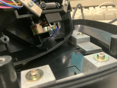
This is the potentiometer, based on variable resistance, correct? The trimmer adjusts the range of it, correct? Therefore I had to decrease its range to minimum to make it work. So I should perhaps measure the middle pin to the ground and check the resistance range. I start to believe this makes the issue. Worn out potentiometer, jumping to max value in the middle of its range. Or perhaps jumping out of its range (like short circuit)

After measuring, I would spray it with some spray for contacts (I have several of them cleaning dry spray, then lubricant spray for contacts WD40, etc).

Attachments