Roman555 wrote on 2022-12-20, 14:41:
Hi,
Is CMOS battery OK and a clear-cmos jumper set in normal position ?
Yes, they are.
Also I found pictures online of this board that show another clock chip. One I had much more luck finding a datasheet for (w83194R-39). So now having the datasheet for a compatible chip (my MB has cma8864bf-26) I can uld check all the pins.
The voltages are as they should be. The pci clock is being generated by the chip as well as the cpu clocks.
However, there is something "weird" on the sdram clock outputs. Instead of a clock they all have 61khz ringing. Same ringing is present on top of the cpu clock as well as on the CPU_STOP line. Now the CPU_STOP is active low and it should stop both the cpu1 clock and sdram when low. Somehow it is low (with this 60khz ringing on top), but cpu1 is active while all sdram clocks are off.
I measured resistance from the SDram clocks to GND and v+ it looks good at 100k. Do you think the clock chip might be damaged, or something else?
I see the same behaviour with and without ram/cpu.
Edit: Something is definitely pulling CPU_STOP low as I measured the resistance to ground and the moment I power it on it goes from 100k down to 10ohm. So the question is not why sdram clock if off, but why cpu clock is on with this... And why is this being pulled low.
Edit2: I'm now t sure I'm interpreting this right. I noticed my chip has different settings on the rj2 permanent jumper than the "compatible one". I really need its datasheet to be able to deduct anything.
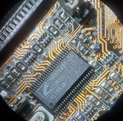
Does anyone know a clock chip named cma8864bf-26 or has its datasheet? Google seems to fail me on this. This is the chip.
I doubt I can do much without a datasheet. What I thought to be CPU_STOP goes to pin 1 of rj2 (the unconnected pin on the left/top).