VOGONS


First post, by majestyk

User metadata
Rank Oldbie
Rank
Oldbie

https://theretroweb.com/motherboards/s/atc-unitron-u3911-v3
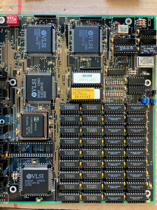
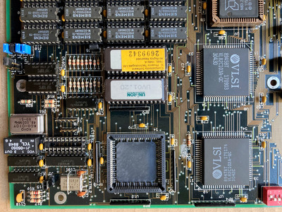
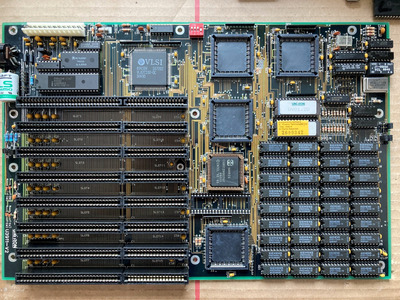
This 286 mainboard was repaired a while ago (VARTA damage) and ever since ran with 1MB RAM (36 DIL 256Kb chips) with parity enabled without any issues.
Here you can see it´s original condition:

unitron3911v2or.JPG
Filename
unitron3911v2or.JPG
File size
277.83 KiB
Views
653 views
File license
Public domain

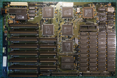
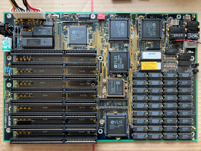
Recently I removed the 256Kb chips to upgrade to 2MB with 18 1Mb chips in BANK0 and everything continued working fine.
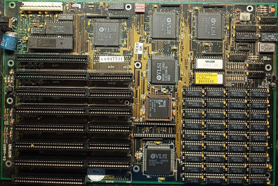
Trouble started when I upgraded to 4MB RAM by adding another 18 1Mb chips in BANK1:
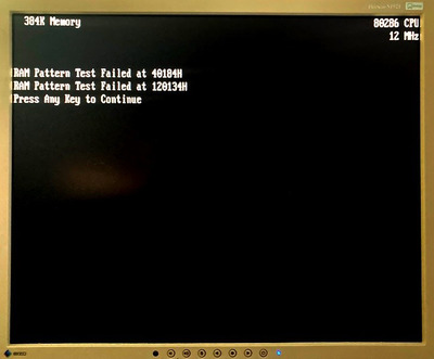
With parity disabled (jumper J11 in position 1-2) everything´s still fine but as soon as parity is turned on I get something like this:

error_par1.JPG
Filename
error_par1.JPG
File size
178.91 KiB
Views
1048 views
File license
Public domain

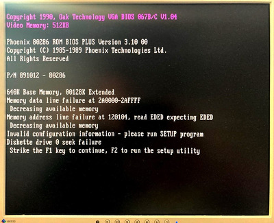
When the system is set to 8MHz instead of 12 MHz, memory count will finish, but as soon as I load any software under DOS, parity errors will be detected and the system halts.

In the meantime I have tried several sets of DIL RAM chips (Siemens, Toshiba and Motorola) in various positions and combinations, at one point the first error message disappered, but the "120104" error persists. (sometimes it´s 120102 or 120100) The DIL chips are running flawlessly on other 286 / 386 mainboards.
I also measured the data and address lines between / among DIL chips and between the DIL chips and the VL82C104 data buffer, also those connected to the 74F10 triple-input NAND gates but I couldn´find any interruptions or shorts.

Filename
VLSI_VL82C104.pdf
File size
667.53 KiB
Downloads
33 downloads
File license
Public domain

->C118 is missing (was broken) but it has no influence on the current issue.
Neither effects the wait states setting (=0 or =1) the errors.

unitron3911v3a.JPG
Filename
unitron3911v3a.JPG
File size
635.35 KiB
Views
1048 views
File license
Public domain
Last edited by majestyk on 2023-09-03, 10:49. Edited 2 times in total.

Reply 1 of 22, by majestyk

User metadata
Rank Oldbie
Rank
Oldbie

There´s still no progress narrowing down the cause of these parity errors.

The "Memory address line failure at" error randomly attains the values 120102, 120104 or 120106. In any case "EDED" is both expected and read.
Replacing whole banks of memory or replacing the DIL chips one by one has no effect.
Contrary to what I wrote in the opening post there´s also an error with just "BANK0" populated.

The only options to increase the siutuation is turning off parity or reducing CPU frequency permanently to 8MHz or using 16-pin 256Kb chips only.

Reply 2 of 22, by Horun

User metadata
Rank l33t++
Rank
l33t++

I have a similar issue on my Protech 286 board but never found a solution

Hate posting a reply and then have to edit it because it made no sense 😁 First computer was an IBM 3270 workstation with CGA monitor. Stuff: https://archive.org/details/@horun

Reply 3 of 22, by majestyk

User metadata
Rank Oldbie
Rank
Oldbie

I´m just testing the current set of DIP chips on a 386 mainboard with Memtest 3.0 to make sure they are not faulty.

If they are 100% functional I wonder why the issue is depending on frequency. Maybe the signal quality is deteriorating at 12MHz.
My 20 MHz oscilloscope should be able to display the signals, but I have no idea where to start...

Reply 4 of 22, by majestyk

User metadata
Rank Oldbie
Rank
Oldbie

All the DIL chips have been thoroughly tested in the meantime, there was not even one single error being detected.
I also can almost certainly rule out any bad soldering joints or interrupted traces.
Cooling the chips with coolant spray before startup revealed that memory check and running software caused no errors when the system controller chip "VL82C101B-QC" was (heavily) cooled before starting the system.
I removed it and put a PLCC84 socket in it´s place to continue the tests as soon as I can get my hand on another working 82C101.

unitron3911v3d.JPG
Filename
unitron3911v3d.JPG
File size
1.13 MiB
Views
928 views
File license
Public domain

I also need to find a spare PAL chip, because the mainboard came with a defective Acer "C13-10-1BS 8946". (I wonder if the last 4 digits are just a date code?)

Reply 5 of 22, by maksg

User metadata
Rank Newbie
Rank
Newbie

This is really odd.

Memory data line failure at 2A0000-2AFFFF
Memory address line failure at 120103, read EDED expected EDED

Did I understand correctly that the BIOS during the memory test read what was expected, but perceived it as an error?
Because EDED == EDED, isn't?

Reply 6 of 22, by majestyk

User metadata
Rank Oldbie
Rank
Oldbie

It´s like throwing a dice:
Sometimes it reports an error when the expected value differs from the read value and sometimes it complains when both values are identical.

The VL82C101 contains "two 16L8 PALs for memeory decoding" so I hope that things are being messed up there.

Reply 7 of 22, by maksg

User metadata
Rank Newbie
Rank
Newbie

Given that this VL82C101 installed into the socket may mean that it might be a potentially unreliable part.
p.s. I have also a quite similar 286 MB based on VLSI. And now I'm torn by curiosity and want to try to upgrade it to 4 MB, maybe I will run into similar problems.

Attachments

  • vlsi_286.jpg
    Filename
    vlsi_286.jpg
    File size
    968.17 KiB
    Views
    849 views
    File license
    Public domain

Reply 8 of 22, by majestyk

User metadata
Rank Oldbie
Rank
Oldbie

It should work without any issues on your board.

I have three different mainboards with this exact chipset (all 12 MHz) and they all run hasslefree with 4MB (both DIL chips and SIPP RAM sticks).
It´s just this Unitron board that´s giving me hell.
Today I replaced all 4 chips VL82C101, 102, 103 and 104 (except the peripheral controller VL82C100) with a known good set from one of my working boards - - to NO avail.
At the moment I´m running out of ideas.
In 8 MHz mode the system seems to work 100%, as soon as I switch to 12 MHz the troubles begin.

Reply 10 of 22, by majestyk

User metadata
Rank Oldbie
Rank
Oldbie

After removing each old (soldered and resoldered) chip I soldered a socket in it´s place and inserted a known good chip from a different mainboard.
Nothing changed. (I´m quite sure I can rule out any bad soldering joints at the sockets.)
At the moment I´m testing with a MR.BIOS and I get two errors when it tests memory:

unitron3911v3err1.JPG
Filename
unitron3911v3err1.JPG
File size
38.97 KiB
Views
804 views
File license
Public domain

The hex-values are not always the same. The 3 digits after 40 in the first line and after 120 in the second line vary randomly. I assume "H" denotes Hex values here.

Sometimes there´s a third message: "Banks Decode to Same Location: 2E0000H and 2A0000A"

Since it depends on frequency I wonder if this could be some termination issue?

Reply 11 of 22, by maksg

User metadata
Rank Newbie
Rank
Newbie

Can you suggest 1M 18 pins DIP DRAM chips? At least which you are having and used.
Presently I could find only those:

Siemens HYB511000A-70 DIP-18 (from your picture)
Samsung Km41c1000bp-8 18-pin DIP 1 Meg 80ns Dram
Samsung KM41C1000AP-8 1M CMOS RAM DRAM 41c1000 80ns DIP-18
NEC UPD421000C-70
M5M41000BP-8L
Hitachi Hm511000P-10S
GM71C1000B-70 1MBit DRAM Memory DIP18 GOLDSTAR

p.s. I checked your pictures and realized that you installed that socket. (Before reading your last post) Sorry for the silly conclusions.

Reply 12 of 22, by majestyk

User metadata
Rank Oldbie
Rank
Oldbie

I can add
Toshiba "TC511000AP-70" and
Motorola "MCM511000AP80"
to the list.

I replaced the main Oscillator (48MHz) for fun with a 50 MHz one so the CPU gets 25MHz at it´s CLK2 input and system bus is 8 1/3 MHz.
The system doesn´t even start now most of the times , but it works flawlessly when parity is disabled.
All this is a little incosistent - most mainboards don´t have this jumper, but since 4 x 9 DIL chips are being used I guess parity must be enabled by BIOS.
In the Retroweb documentation there´s a questionmark besides the settings of this jumper and when it´s set to enabled the voltage at the "PAREN" input of the 82C104 is low, with parity disabled it´s high, but it´s an "active high" input.

I now have replaced ALL chipset chips except for the peripheral controller and all logic DIL circuits except a 4069BUP near the RTC and a 74LS00N near the peripheral controller.

There´s a Russian board where the guy who contributed the jumper settings for this Unitron mainboard on Retroweb tells that he assumes Jumper 11 is for turning parity on/off and he seeks a way to test /proove it.
https://www.phantom.sannata.org/viewtopic.php?t=44430

In a reply "Kir17 tells him:
"There is at hand just such a board in a partially working condition, which I "pick" at my leisure. As far as I remember, the top row of memory chips is 9-bit (parity), because the data input/output "rings" to the chipset's parity data output/input (I don't remember the exact chip and pin number, but I can check). Jumper J11 has nothing to do with parity, but sets the regeneration parameters for the RAM (in my opinion, the value of the CAS signal delay after RAS). Without a jumper at all, it is possible that the CAS signal is not formed at all and the RAM "falls"."

If this was true I´ve been hunting a phantom all the time...

...and it would explain why
-on every picture of this mainboard on the web jumper 11 is in position 1-2
-I cannot find any defect

Reply 13 of 22, by maksg

User metadata
Rank Newbie
Rank
Newbie

This is quotation from the URL you posed "There are suspicions that parity can be disabled only by interfering with the circuit board, and the manufacturer does not provide the ability to disable parity." from Kir17 (07.04.2023,12:16). Very similar to the truth. It seems to be the same on my 286 SBC. There no way to disable parity for memory at all, even in BIOS.

But I have a suspicion that in your case you can disable parity by simply removing these chips that are responsible for the parity control from the board at all. Have you tried it?

Last edited by maksg on 2023-09-03, 14:06. Edited 1 time in total.

Reply 14 of 22, by majestyk

User metadata
Rank Oldbie
Rank
Oldbie

There´s basically no need anymore to disable parity. With jumper 11 in position 1-2 the "CAS signal delay" (or whatever) seems to fit the current RAM type and RAM configuration, the systim is running 100% stable and without any errors despite being slightly overclocked.
If this delay time is set wrong it causes the parity errors itself. For the initial configuration with 36 x 256K chips (1MB in total) both settings were operational.

I think parity is forced/enabled by default on all VLSI mainboards with 8+1 DIP-RAM columns / 9-chip SIPP sockets.

Reply 15 of 22, by maksg

User metadata
Rank Newbie
Rank
Newbie

I tried it on my 286. Did not work. It looks like the parity check is hardcoded in the BIOS and can't be disabled. But if we trace the BIOS, then we can disable it programmatically and patch the BIOS. Probably this is the only way. But does it make sense at all? I mean disabling parity control. If there is a parity problem, then the code will run with errors. Right?

Reply 17 of 22, by Horun

User metadata
Rank l33t++
Rank
l33t++
maksg wrote on 2023-09-01, 16:42:

Given that this VL82C101 installed into the socket may mean that it might be a potentially unreliable part.
p.s. I have also a quite similar 286 MB based on VLSI. And now I'm torn by curiosity and want to try to upgrade it to 4 MB, maybe I will run into similar problems.

My Protek is an exact copy of your board and gives a parity error that I never figured out even with switching to known all good ram.
The TH99 /TRW page for it is: TOPTEK 286-SYSTEM BOARD (VLSI) https://theretroweb.com/motherboards/s/unknow … stem-board-vlsi

Hate posting a reply and then have to edit it because it made no sense 😁 First computer was an IBM 3270 workstation with CGA monitor. Stuff: https://archive.org/details/@horun

Reply 18 of 22, by majestyk

User metadata
Rank Oldbie
Rank
Oldbie

I also have this Toptek VLSI mainboard (it was the one I borrowed the chips from). I tested it with both SIPP sticks and DIL chips (4MB) and it worked perfectly.
I guess you have checked all the solderings of the PLCC84 chips carefully / resoldered them all?
My FTK VLSI board wouldn´t start occasionally and I had resoldered all the pins except one angle of a chip that is only 1 cm apart from an ISA slot, and only after I resoldered these remaining 21 pins the issue was fixed.

On my Unitron I cleaned up everything and reseated the original chips:

unitron3911v2e.JPG
Filename
unitron3911v2e.JPG
File size
1.21 MiB
Views
659 views
File license
Public domain
unitron3911v2f.JPG
Filename
unitron3911v2f.JPG
File size
1.21 MiB
Views
659 views
File license
Public domain