HOLY CRAP
Now that is a discovery and thanks for it.
My unit has the same riser card (also with solider in TC4), so this is definitely going to be added high on my retrocomputing projects list. As well as a case mod to make it easier to change out the SD card boot drive.
I just matched the physical size up. I have no idea what UF/V they were.
I can't PM yet, but Cyclone3d when I populated my board last night, the computer wouldn't boot at all with or without the sound card. Any chance I could pay you to populate mine? labor/materials/shipping I'm based out of MI.
I have figured out what the problem is with the AW744-L2 card and the HP T5720 thin client.
It is PCI bus noise.
Fully populating the capacitor places on the PCI riser card completely fixes the issue. I am guessing this will also fix issues with "compatibility" with other cards as well. It should also significantly clear up the audio output if you are using a different sound card.
So, I'm in the same boat here with my Fujitsu Futro S300. Neither my "Creative" CT4810 (AudioPCI) nor my AW840 / CMI8738/PCI-SX want to work with it (both cards are known good - actually the Creative DOS drivers init the card and upload the wavetable sample ROM sucessfully, but no sound output is to be heard. The CMI card just plain won't initialize.)
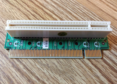
Fortunately the solder pads & holes are all nice and clean, but unfortunately, there's no published values for the caps anywhere. This is the riser:
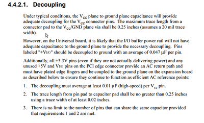
I'm struggling with this, also. I have two T5720 machines with the PCI riser + expansion cases. I would really like to populate the risers to spec, if possible. I took a look at the PCI Local Bus Specification version 2.2 (That's the version I found through Google.) and in section 4.4.2.1 I found (apologies for the screenshot; the PDF uses embedded fonts):
Is there a way to determine what PCI version the T5720 adheres to? Does the T5720 support 3.3V, 5V and universal PCI cards?
Are the intended capacitors found on this PCI riser meant to deal with the decoupling of expansion boards or are these used for some other reason? (I would have assumed that the decoupling capacitors would be found on the PCI expansion board itself, not on this riser.)
Is there any indication that the PCI boards that work vs. the PCI boards that don't work has something to do with being a 5V, 3.3V or "Universal" expansion board?
If these capacitors are meant for decoupling, the PCI spec (table 4.13) suggests that there should be as many as 27 capacitors (pins 5A, 5B, 6B, 8A, 10A, 16A, 19B, 21A, 25B, 27A, 31B, 33A, 36B, 39A, 41B, 43B, 45A, 53A, 54B, 59A, 59B, 61A, 61B, 66A, 70B, 75A & 79B) but there are only 10 (if I counted correctly) capacitor solder points on the PCI riser. Am I reading the spec wrong?
The capacitor values are not critical. Only thing I would worry about is making sure the rated voltage is equal to or higher than the PCI voltage.
I already posted what I used when I found the fix... at least for the electrolytic capacitors. The SMD that I used, I just matched up the size that would fit.
For all I know, a single capacitor would fix the problem but I just populated the cap positions on the riser.
Are any of the capacitor pads connected to data pins on the PCI slot? Termination impedance will generally be more critical than power plane decoupling.
I'll have to double check, but I don't think so.. at least not for the electrolytic capacitors. That is how I determined where to use 6.3v and 16v caps.
I'll have to double check, but I don't think so.. at least not for the electrolytic capacitors. That is how I determined where to use 6.3v and 16v caps.
Thank you for the continued help. Can you explain the above statement: How did you determine where to use 6.3V & 16V caps?
I tried this mod. I used 47 pF surface mount capacitors and used capacitance and voltage ratings for the electrolytic caps as described in this thread.
I tested the board with a friend who is an Electronics Engineer. With multimeter in hand, we actually de-soldered and re-soldered a few caps thinking that we had a solder bridge. (I'm ok at soldering but not the best.) After everything looked good, I put the riser into a known working system with a known working PCI graphics card.
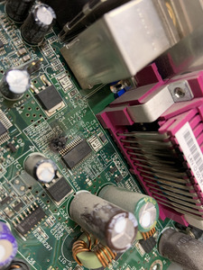
The board caught fire. The flames were probably about 2-3 cm high. High enough that the flames scorched the parallel port connector, as you can see in the picture. I was able to blow out the fire before anything worse happened. I shouldn't have powered this device on while it was laying on a carpeted floor! Luckily, there was no further damage beyond the machine.
I don't know what the cause of the fire was. Likely, it was a faulty job on my part but given the oversight of an EE, I'm not sure. Just wanted to post this here to warn others to be careful. If you do this mod, at least consider powering the system on somewhere safer, like a garage.
I'll have to double check, but I don't think so.. at least not for the electrolytic capacitors. That is how I determined where to use 6.3v and 16v caps.
Thank you for the continued help. Can you explain the above statement: How did you determine where to use 6.3V & 16V caps?
zolliwrote on 2020-11-03, 18:43:I tried this mod. I used 47 pF surface mount capacitors and used capacitance and voltage ratings for the electrolytic caps as de […] Show full quote
I tried this mod. I used 47 pF surface mount capacitors and used capacitance and voltage ratings for the electrolytic caps as described in this thread.
I tested the board with a friend who is an Electronics Engineer. With multimeter in hand, we actually de-soldered and re-soldered a few caps thinking that we had a solder bridge. (I'm ok at soldering but not the best.) After everything looked good, I put the riser into a known working system with a known working PCI graphics card.
The result:
burned_motherboard.jpg
The board caught fire. The flames were probably about 2-3 cm high. High enough that the flames scorched the parallel port connector, as you can see in the picture. I was able to blow out the fire before anything worse happened. I shouldn't have powered this device on while it was laying on a carpeted floor! Luckily, there was no further damage beyond the machine.
I don't know what the cause of the fire was. Likely, it was a faulty job on my part but given the oversight of an EE, I'm not sure. Just wanted to post this here to warn others to be careful. If you do this mod, at least consider powering the system on somewhere safer, like a garage.
Did you try to use this riser in a different system than it came with?
From the one pic, it also looks to me like there was a bulging capacitor on the motherboard.
Did the PCI card work in that same computer before you tried it with the riser?
I am having a similar problem with all of my PCI sound cards in my Neoware CA10 thin client, including an AOpen AW744L II. What I don't know is if the issue is simply PCI bus noise or if it's the lack of -12V on the PCI slot. More details in the thread.
Also, my riser card has more than just unpopulated caps - there's a spot for an IC, an inductor, and some resistors too. I have no idea what to put there.