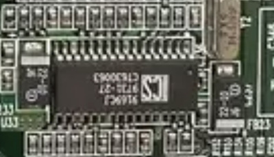
Here is your clock gen, it can tell us if higher fsb is supported if you can get a better pic
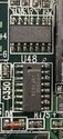
Here appears to be your multiplier settings which you probably already know (you’ll want to set 2x for a k6-3/2+/3+ To get 6x)
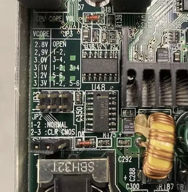
Here are your voltage settings as you know,
Your board designers weren’t very kind to you.
You appear to only have these options
I’ll decipher their actual meaning here
Your base voltage is 2.8v (all off)
1-2 gives you +0.1v
3-4 gives you +0.2v
5-6 gives you +0.4v
I’m betting that one of those chips by the donut shaped coils is your voltage regulator controller but need better pic
I’m also betting that there is a half way decent chance that the designers simply hard shorted your +0.8v option, so if you can get a better pic of those chips we may be able to look up the data sheet and find out which resistor or leg you need to desolder to get down to 2.0v if my guess is correct
The good news is your power circuitry looks nice, large heatsinks with switching regulators. Very nice.
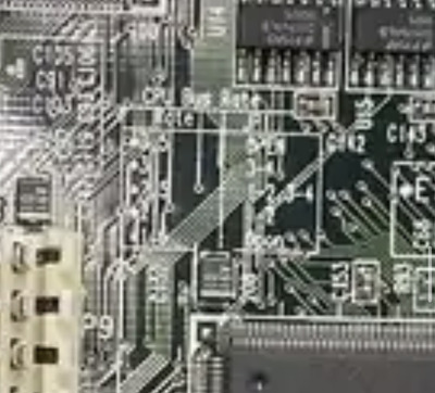
I don’t see a option for your fsb (a jumper anywhere) do you see one?
Looks like you have some onboard ram. Which you may actually consider desoldering and putting all your ram in the provided slot. Because you should be able to get 128mb in the slot alone and with better chips. Otherwise you’ll be limited to 64mb plus whatever is on the board. (Your chipset supports max 128mb and with onboard plus 128mb in slot you’ll probably get errors)
Edit: I see snufkin beat me to it, and seems to have been able to read your image. (My phone may be compressing the images)
You should be able to do this mod if the data sheet shows the option for it, snufkin has walked me through these mods a few times. If willing, follow snufkin’s instructions and we may see 2.0v and 75mhz/83mhz before you know it 😀