VOGONS


Reply 20 of 35, by a_h_adl

User metadata
Rank Newbie
Rank
Newbie
Kahenraz wrote on 2021-09-23, 16:12:

The MOSFETs are pretty cool when paired with a 500Mhz Celeron but extremely hot with a 1.4Ghz Pentium 3. I installed little copper heatsinks on them to help. I wonder if they will be pushed even harder with the lower voltage.

The chip I ordered was through Aliexpress and is estimated to arrive sometime next month. I'll update this thread when I swap out the chip for testing.

It would be nice to see if chip swapping has worked or not.

Reply 23 of 35, by rasz_pl

User metadata
Rank l33t
Rank
l33t
Kahenraz wrote on 2022-07-28, 07:28:

Unfortunately, my P2B died suddenly while in storage before I could try this modification.

My ASUS P2B motherboard died suddenly

short on the diode means mosfet is shorted, I wouldnt give up on P2B

Open Source AT&T Globalyst/NCR/FIC 486-GAC-2 proprietary Cache Module reproduction

Reply 24 of 35, by Kahenraz

User metadata
Rank l33t
Rank
l33t
a_h_adl wrote on 2022-07-28, 10:30:

That’s sad. Have you checked the main regulator? I had two other mainboatds (not P2B’s tho) but chacking the main feeding circuit fixed them.

Which component is that?

Reply 25 of 35, by rasz_pl

User metadata
Rank l33t
Rank
l33t

you can directly compare P2B 1.10 and 1.12 from manufacturing files (Fabmaster Test Expert) https://www.xwfix.com/?s=asus+p2b you will need https://openboardview.org/ to view the files. *.BOM includes detailed list of all components, sadly 1.10 revision is missing contents of this file.
Main difference seems to be addition of Chassis Fan header relocated Chassis Fan header to make room for second VPANEL header and VCore jumper - from what I remember this bumped Vcore by 0.1V or something like that. Sadly cant find manual for 1.12.
Interestingly P2B already had VID0-4 configuration jumper block ready! but its unpopulated and disabled by soldered R30A and RN99 (0 ohm jumper links). Removing those two will enable VID jumper block. I clearly remember using masking tape on three VID pins to manually change voltage on my Celeron 300A to 2.2V on P2B. Missing forest for the trees, 24 years later I finally see the VID pins waiting for me to mod them back on the motherboard 😀

1 why would Asus made an effort of implementing full Vcore override jumper block, and then disabling it with 0 ohm resistors?
2 I also realized VID0-4 pins go to HWmon chip WINBOND W83781D https://www.kernel.org/doc/html/v5.9/hwmon/w83781d.html https://pdf1.alldatasheet.com/datasheet-pdf/v … ND/W83781D.html The only thing this chip does with VID signals is report them back, they are wired to dedicated Inputs instead of universal I/O. What a Huge missed opportunity for implementing soft voltage control Bios menu! 🙁 (Btw Asus boardview files have this chip U6 pinout reversed by 180 degrees, oopise).

Open Source AT&T Globalyst/NCR/FIC 486-GAC-2 proprietary Cache Module reproduction

Reply 26 of 35, by Kahenraz

User metadata
Rank l33t
Rank
l33t

Good news! I managed to buy another P2B to replace the one that died. The research can now continue!

Curiously, this is the exact same revision as my other board, 1.10, but comes with the HIP6019BCB PWM controller, exactly what I had planned to swap in.

20221014_144321_resize_17.jpg
Filename
20221014_144321_resize_17.jpg
File size
318.84 KiB
Views
897 views
File license
CC-BY-4.0
20221014_144605.jpg
Filename
20221014_144605.jpg
File size
206.01 KiB
Views
897 views
File license
CC-BY-4.0
20221014_144558.jpg
Filename
20221014_144558.jpg
File size
345.25 KiB
Views
897 views
File license
CC-BY-4.0

Reply 27 of 35, by Kahenraz

User metadata
Rank l33t
Rank
l33t

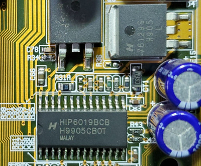
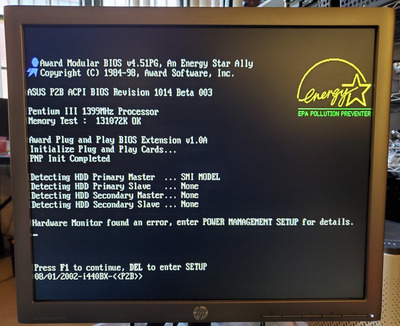
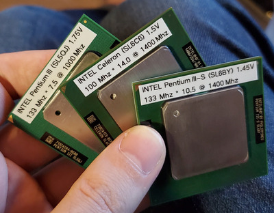
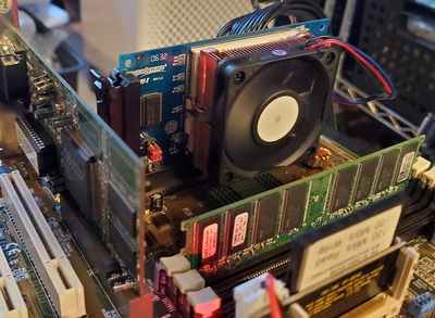
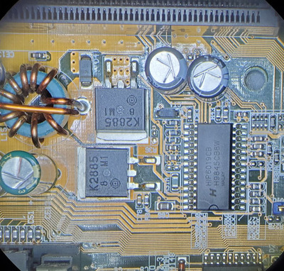
With this revision and PWM controller, I can confirm that both Coppermine and Tualatin are supported, and validated with a Pentium 3 SL3XK (100/650), SL5QJ (133/1000), and SL6BY (133/1400). Tualatin chips worked with and without a Tualatin/Coppermine interposer, as well as with and without a Tualatin-specific slocket adapter (Upgradeware Slot-T).

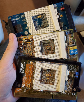
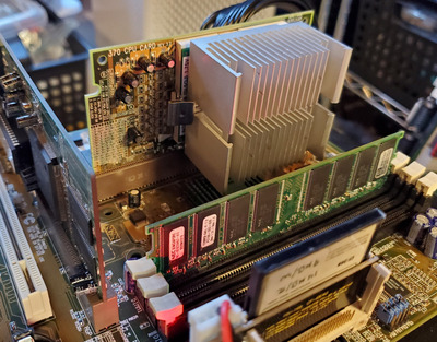
I was able to use a non-interposer Tualatin (SL5QJ) with one of my voltage-selecting slocket, but it did not work with another ASUS branded one. I don't know why one would work but not the other. It appears that there is more to it than just a voltage selection. I don't believe this unbranded "370 CPU Card" has any Tualaton features, as there are only discreet components on it.

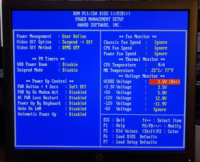
Although it may have worked with other slockets, only my Upgradeware Slot-T has a jumper setting for 1.45V, although I was able to run this chip at 1.8V previously on my other P2B motherboard, as the PWM controller wasn't able to POST with anything lower.

I was not able to get the system to POST with a Tualatin Celeron SL6C6 (100/1400). I only have one of these chips, so I can't confirm that this chip is working, or is incompatible.

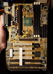
This is a great result for the P2B, and shows that, with a compatible PWM controller and VRMs, can support Coppermine and Tualatin up to 133/1400Mhz.

20221014_163041_resize_90.jpg
Filename
20221014_163041_resize_90.jpg
File size
251.42 KiB
Views
887 views
File license
CC-BY-4.0
20221014_163113_resize_61.jpg
Filename
20221014_163113_resize_61.jpg
File size
280.12 KiB
Views
887 views
File license
CC-BY-4.0
20221014_170045.jpg
Filename
20221014_170045.jpg
File size
726.4 KiB
Views
887 views
File license
CC-BY-4.0
20221014_170055.jpg
Filename
20221014_170055.jpg
File size
1.1 MiB
Views
887 views
File license
CC-BY-4.0
20221014_165919.jpg
Filename
20221014_165919.jpg
File size
1.09 MiB
Views
887 views
File license
CC-BY-4.0

Reply 29 of 35, by Sly_Botts

User metadata
Rank Member
Rank
Member

I own a P2B rev 1.10 with bios 1012. Yesterday I tried a slotket with a Coppermine 933mhz 133fsb chip. the board maintained 100fsb and ran the CPU at 700mhz. Ran quite well. With a voodoo 3 3000 it scored 4071 in 3d Mark 200 and showed noticeable fps improvement in some games. I now have a 900mhz 100 FSB 370 Coppermine on the way. It will my main cpu for this system.

It is possible to commit no errors and still lose. That is not a weakness, that is life.

Reply 30 of 35, by Kahenraz

User metadata
Rank l33t
Rank
l33t

Put your finger on the VRMs. On my dead P2B, they got unbearably hot to the touch when used with a fast Coppermine or Tualatin, and may have led to its early demise. In contrast, the VRMs on this new board remained slightly above ambient, even with a 1.4Ghz Tualatin.

If they become too hot to touch, then your CPU pairing might be risky to their long term health.

Last edited by Kahenraz on 2024-03-05, 06:48. Edited 1 time in total.

Reply 31 of 35, by Kahenraz

User metadata
Rank l33t
Rank
l33t

Following up on this. I tried replacing the MOSFETs, which I thought was the problem, but the board remains dead. I don't think that the PWM controller is the problem, so I didn't bother replacing that.

I took some photos of the repair work, which I can still share. I would still really like to try this mod on a working motherboard, to confirm it. Maybe if I get another P2B in the future.

It was still very good practice. Getting these gigantic surface mounted TO-220 parts off of the board is really difficult. Not only is there a large surface area and ground plane that absorbs heat, but there is also surface tension under the part that makes it hard to lift off. Every time I got them to break free, they would fly off in some random direction, like into my lap. At 400C. Good times.

To clarify for those who haven't read the other posts in this thread, the P2B motherboard I was going to do this mod on died. I thought that it might have been the MOSFETs, which is what I replaced here, but it didn't fix it. The MOSFET and PWM replacements are supposed to add support for lower voltage Coppermine and Tualatin CPUs.

20221027_200116_resize_65.jpg
Filename
20221027_200116_resize_65.jpg
File size
219.31 KiB
Views
828 views
File license
CC-BY-4.0
20221027_200133_resize_86.jpg
Filename
20221027_200133_resize_86.jpg
File size
93.37 KiB
Views
828 views
File license
CC-BY-4.0
20221027_201321_resize_29.jpg
Filename
20221027_201321_resize_29.jpg
File size
226.11 KiB
Views
828 views
File license
CC-BY-4.0
20221027_204520_resize_27.jpg
Filename
20221027_204520_resize_27.jpg
File size
333.28 KiB
Views
828 views
File license
CC-BY-4.0
20221027_212312_resize_96.jpg
Filename
20221027_212312_resize_96.jpg
File size
143.5 KiB
Views
828 views
File license
CC-BY-4.0

Reply 33 of 35, by rasz_pl

User metadata
Rank l33t
Rank
l33t
Kahenraz wrote on 2022-10-28, 03:11:

Following up on this. I tried replacing the MOSFETs, which I thought was the problem, but the board remains dead. I don't think that the PWM controller is the problem, so I didn't bother replacing that.

To clarify for those who haven't read the other posts in this thread, the P2B motherboard I was going to do this mod on died. I thought that it might have been the MOSFETs, which is what I replaced here, but it didn't fix it.

you replaced mosfets without diagnosing the defect? 😐
put an empty slotket with Voltage override jumpers set to 2.0V in the Slot1 and measure voltage on the output of those mosfets, measure Vio 3.3V (the other big inverter on the board), Vtt 1.5V (transistor in the corner of slot1 and AGP slot)

Open Source AT&T Globalyst/NCR/FIC 486-GAC-2 proprietary Cache Module reproduction

Reply 34 of 35, by Kahenraz

User metadata
Rank l33t
Rank
l33t
rasz_pl wrote on 2022-10-28, 04:39:

you replaced mosfets without diagnosing the defect? 😐
put an empty slotket with Voltage override jumpers set to 2.0V in the Slot1 and measure voltage on the output of those mosfets, measure Vio 3.3V (the other big inverter on the board), Vtt 1.5V (transistor in the corner of slot1 and AGP slot)

As much repair work as I do, I have very little experience diagnosing more complex faults with electrics beyond swapping parts. What you have suggested sounds very reasonable, and something I will try in the future. This thread has been around for some time, and there weren't any other useful suggestions, so I went ahead with what I knew how to do.

I planned to replace these anyways, as part of the upgrade, so there wasn't any reason not to. I was also good practice. I'm still experimenting with different techniques for removing these very large components.

Reply 35 of 35, by Kahenraz

User metadata
Rank l33t
Rank
l33t
mockingbird wrote on 2022-10-28, 04:12:

Can you post a close-up of the Korean adapter installed on your chip please? I installed one on my SL6BY and it no longer works.

I took some photos for you. Let me know if you need anything else, or if they are unclear. I am taking pictures from my phone, which can difficult when it comes to small components and fine details.

See here:

Photos of my Tualatin interposer