rasz_pl wrote on 2022-12-11, 16:50:see that plated hole on the top? theres even a fuse between it and ground […]
Show full quote
see that plated hole on the top? theres even a fuse between it and ground
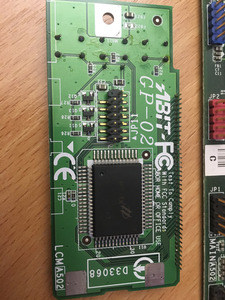
get that multimeter out and measure
-supply voltage, ground (pin 6) to pin 8
-bias, ground to pin 9
Pin 9 to ground voltage: 3,53v.
Pin 9 to ground bias: 1
Pin 6 to ground voltage: 0,0v
Edit: Pin 8 to ground: ca 3,7v
I was counting the chip's legs from left to right, if you look at the PCB in the direction of the "ABIT GP-02" text not being rotated.
This was all tested during the pc on.
Unfortunately, there was no way for me to do this without using ground from the pc motherboard usb pins, because i don't have 3 hands, so there's probably something wrong with the results.
However, for a few seconds while booting the pc this time, a few characters on the display seemed sharper. Then it went back. Going by that alone i can see this being a problem with supply of power rather than the display itself.
