poprhythm wrote on 2023-06-06, 19:38:
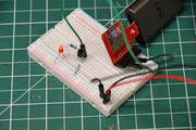
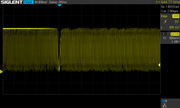
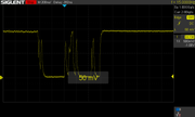
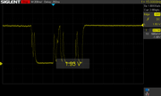
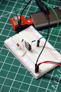
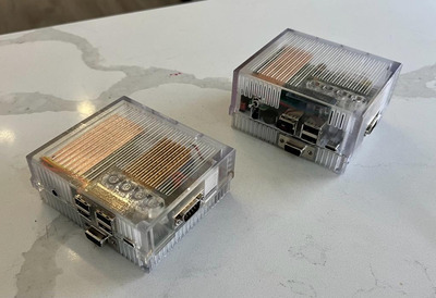
I got one of these guys to experiment with. Hooked up the circuit that Aaron had linked to and it worked right away. Used a 2N3906 PNP transistor. Either pin 2 or 3 works, I can't tell a difference for disk activity. Pin 2 drops from ~2.48v at high to 1.5v at low, while pin 3 drops to ~2.2v at low.
Not sure I understand what's going on here... You're talking about measuring the voltage between GND and either pin 2 or pin 3 of the microSD card? I hope you're using an oscilloscope - if not, you're going to see an average of the signal jumping back and forth between ~3.3V and 0V.
poprhythm wrote on 2023-06-06, 19:38:I looked at this calculator for transistor resistor values between signal and base, but I don't know the load resistance or curr […]
Show full quote
I looked at this calculator for transistor resistor values between signal and base, but I don't know the load resistance or current for the SD cable signal. I attached a multimeter on the µA setting between pin 2 and ground which reported 800µA when the card wasn't being accessed. But this test seemed to interfere with the signal quality - it produced read errors when trying to copy a file. Anyway, I plugged in iL = .8A, VCC = 5V, Vi = 2.5V (or 3.3?) to the calculator, which split back the Rb should be 31 ohm.
I then did some trial and error with different resistor values, from none up to 10K ohm. It worked every time, although the LED definitely got dimmer above 1Kohm.
Edit: so OK, so this electronics newb got my unit conversion wrong on the µA to A. I plugged in .0008 and got 30K ohm. I’ll give that a shot, and maybe adjust the LED resistor down if it looks like it’s not getting enough juice.
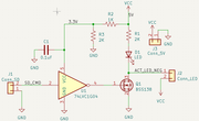
You seem a bit confused about how this works, let me try to explain! 😀 First, LEDs: they're diodes and will happily gobble down all the current you give them, so you need to control that yourself. For a normal 5V-rated LED, something like 2-10mA through the LED works pretty well. In order to achieve that, take the vcc, subtract the LED's rated forward voltage drop (normally 1.7-2.3V, read the specs) and divide the result by the current you want, in Amps. So for instance, (5V-2V)/0.01A = 300 ohms. That's the resistor value you want in series with the LED, and that should be what decides its brightness, not the transistor's saturation level (which you want fully saturated when active).
As for the value of the transistor's base resistor, yeah that calculator gives you an estimate - but you have to find the correct Hfe (current gain) for a particular transistor and circuit setup. Datasheet is your friend. Also, the "Vi"on that calculator should be 3.3V.
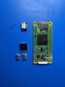
Btw, if I'm looking at your photo correctly, you've hooked up the transistor the wrong way - for a PNP transistor, the collector should go through the load (resistor+LED) and then to GND, whereas the emitter should be connected to VCC.
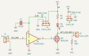
Finally - like we discussed earlier in this thread, it's probably not a good idea to connect a sensitive signal to anything that'll draw a meaningful amount of current, like the base of a transistor. It'll likely be just fine, but no guarantees. What you want instead is a high-impedance input. That'll be the gate of a mosfet - either a discrete one or the input of a logic gate.
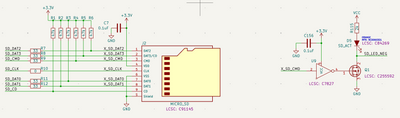
For my next ITX-Llama board, I'll try hooking up the CMD line (active-low) of the microSD connector to the input of an inverter, and then use its output (active-high) to drive the gate of an NPN mosfet that'll be able to supply the necessary current for both an internal and an external activity LED.
(For anyone wanting to point out I could just use a single PNP mosfet instead, yeah but it's hard to find one with the correct Vgs(th) levels when driven by 0-3.3V and controlling 5V 😉 )