pentiumspeed wrote on 2023-10-19, 16:33:
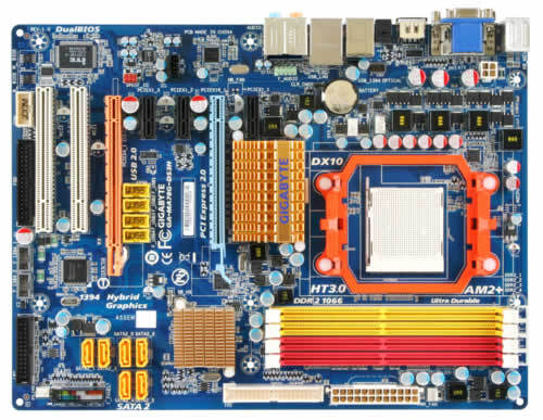
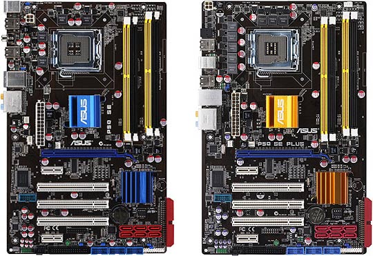
Is this your motherboard in this picture (the blue one)?
I consider all boards with heavy power (those AMD and P4 CPUs) using 2 phase VRM insufficient and I had instability in past. When I moved on to boards with 3 phases or more, I had stability back. 2 phase VRM is also make more noise if you are all about quality of audio. 3 phase and at least 5 to 6 bigger diameter capacitors, not the smaller ones and lot more MLCC capacitors.
Cheers,
On the element base of those times, one phase had a power of approximately 35 watts. For a 100W CPU, two phases is not enough, but I'm not a fan of Brisbane and Windsor. This board running with mobile Turion 😀
Strictly speaking, the current through the capacitors depends on the number of phases. The more there are, the less current.
You can design 1 phase at 100 Watt, but this will not be optimal.
Hoping wrote on 2023-10-19, 17:04:
@shevalier.
It would be interesting to have a calm, detailed explanation, avoiding technicalities as much as possible, about the real importance of ESR and even ESL, and also why a high capacitance is not the most important thing, and the reason why the more expensive the hardware is, more MLCCs and SMD polymer capacitors instead of radial ones you find;
Strictly speaking, the time constant R*C is important for output capacitors. This is the product of capacitance and ESR. The frequency compensation (stability) of the power controller error amplifier depends on this, especially with two-pole compensation. You need to read about this either in textbooks or datasheets with application notes.
There is also a formula for ripple voltage. This is equal to the product of ESR and the change in current. For the same ripple voltage, you need either a smaller ESR or a smaller change in current (more phases).
It’s better to read about this in the application notes
PS. For square voltage, the maximum power of harmonics will be at the third. Those. at a conversion frequency of up to 100 kHz (typical for those years), this will be up to 300 kHz. The capacitance of the MLCC capacitors must be very significant at this frequency. These are not the typical 0.1-1 µF, these should be capacitances of a hundreds µF.
In those years, it was expensive and inaccessible.
Therefore, it is quite pointless, given that polymer capacitors still reach these frequencies.
An example that I know personally is the Fujitsu D3128-b25 that uses many fewer radial capacitors than are usually seen in the VRM, but on the back it has several SMD polymers.
SMD capacitors are placed and soldered at the same time as everything else. Radial capacitors are often placed by hand and soldered in a separate technological process using selective soldering. But it is advisable to glue heavy parts before soldering so that they do not move out of their places.
It's a question of optimizing production, which type of parts is cheaper to use.
From a practical point of view, a general use polymer capacitor is approximately equal to the ultralow ECP electrolyte from 20 years ago.
So the rule of thumb is 0.5~2 the original capacity almost always works well. The appropriate color and diameter, of course.
Otherwise it looks ugly
Aopen MX3S, PIII-S Tualatin 1133, Radeon 9800Pro@XT BIOS, Audigy 4 SB0610
JetWay K8T8AS, Athlon DH-E6 3000+, Radeon HD2600Pro AGP, Audigy 2 Value SB0400
Gigabyte Ga-k8n51gmf, Turion64 ML-30@2.2GHz , Radeon X800GTO PL16, Diamond monster sound MX300


