Spent the last weekend and yesterday afternoon building a new logic board for my SEGA MegaCD.
The previous one had severe cap leakage, leading to corroded solder joints that had completely let go on one side of the QFP.
My attempts to reflow it just started to cause bent pins and screwed up pads, as fighting against that amount of corrosion is futile.
So I decided to hold off on trying to continue to fix the original board, and wait for a new JLCPCB order of various PCBs and 3D printed things to tack on some new logic boards, as there do exist modern open source recreations of the main (Mega)CD logic boards.
However, someone on a Dutch classifieds site was selling some of their extras for 10 bucks a pop, so I decided to just buy that.
It was a HASL board, where I would probably have sprung for ENIG, but to be honest, the MegaDrives themselves are HASL (other than a few with carbon coated pins on the extension connector), and it doesn't seem like the MegaCD expansion connectors are all having metal reaction issues with those boards, so eh, it'll be fine.
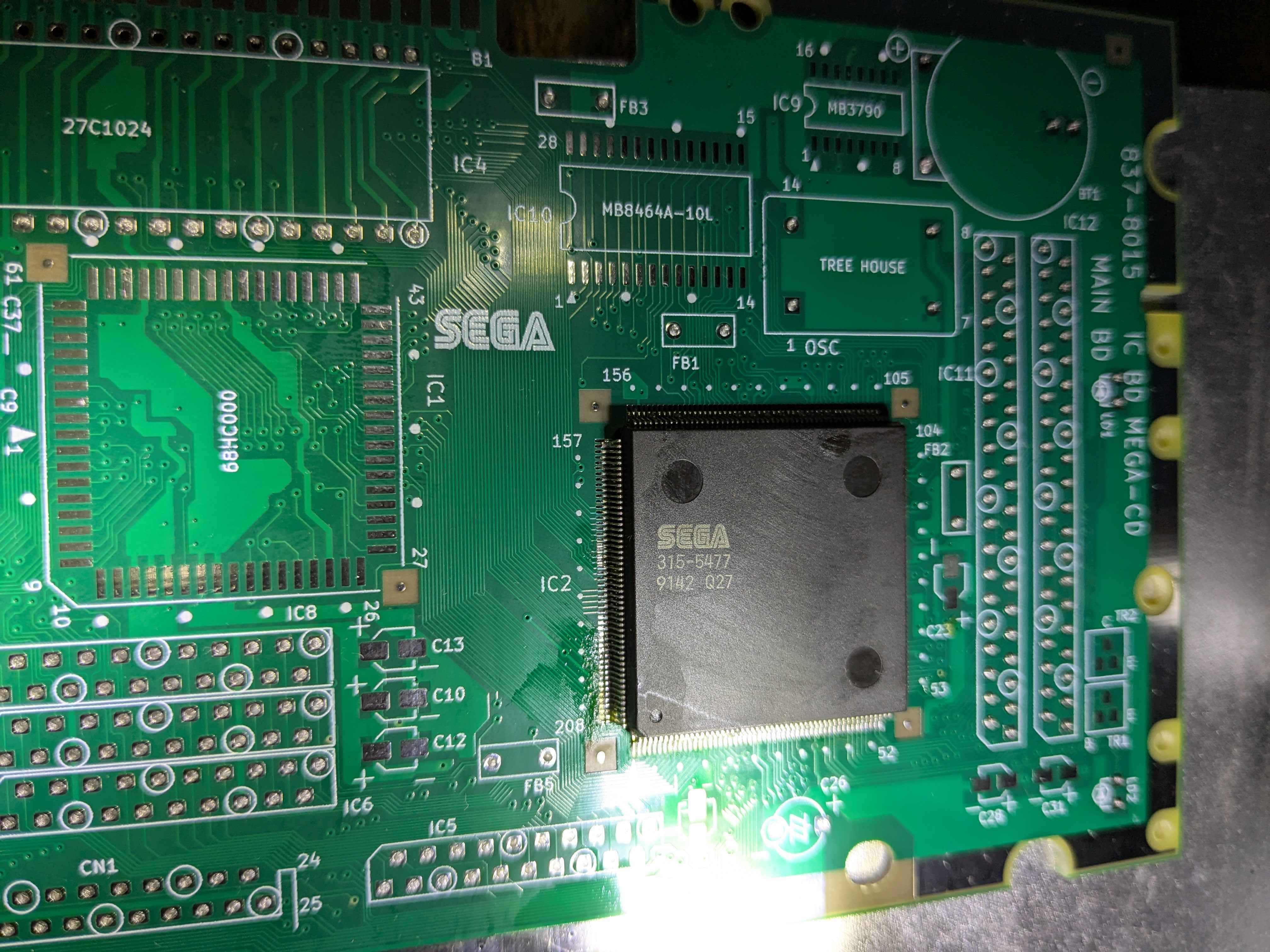
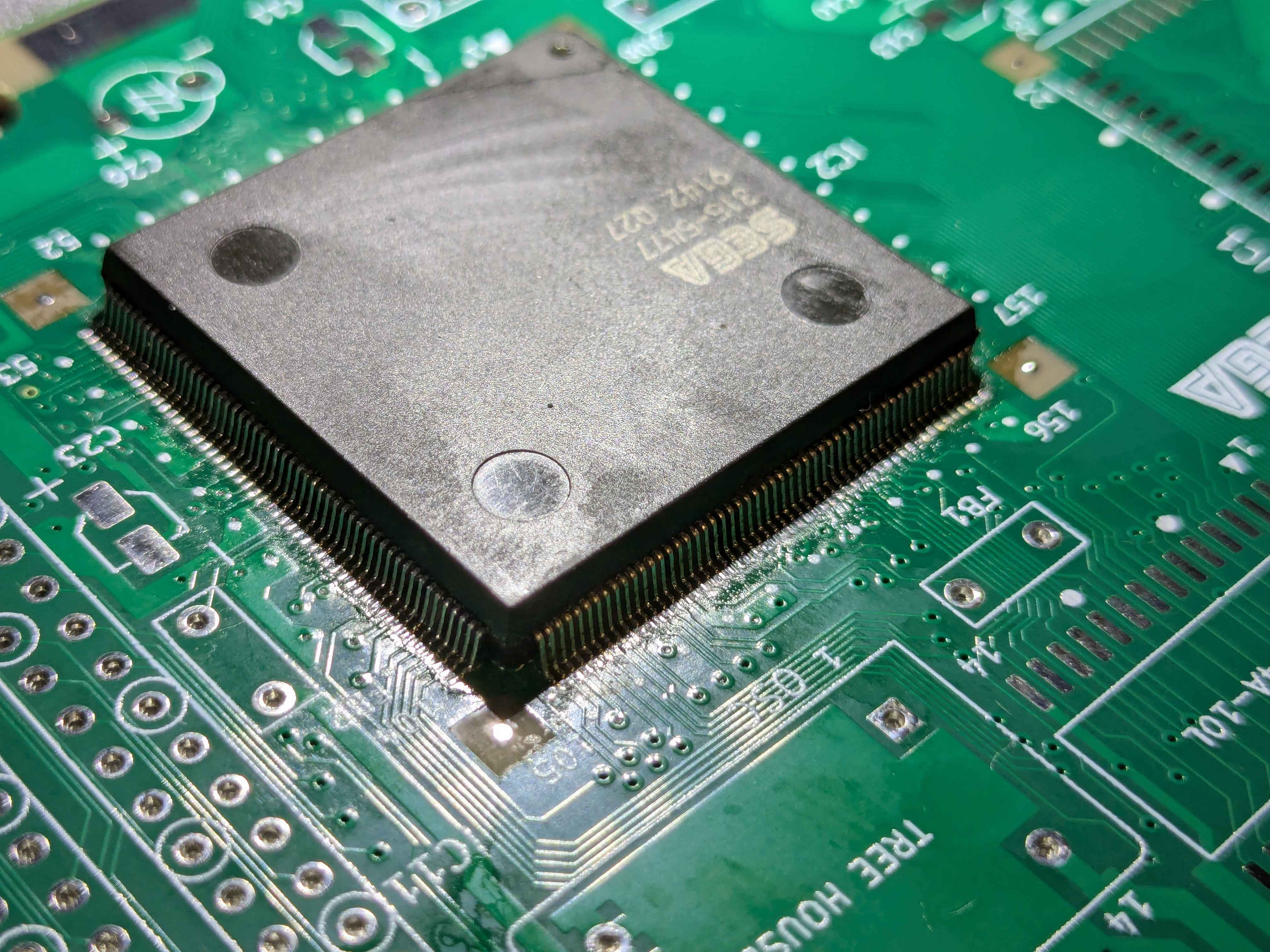
Once the board was under the microscope, the first thing I tackled was the ASIC.
This will be the trickiest component to get soldered down correctly, so I want this done before continuing with the rest.
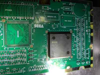
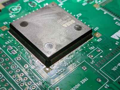
(Click on the thumbnails for full resolution pics)
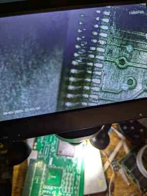
That went well, even the slightly malformed pins at least have a solid solder connection, and are not bridged together.
I have some footage from the microscope of soldering one of the sides of the QFP here, if it is of any interest.
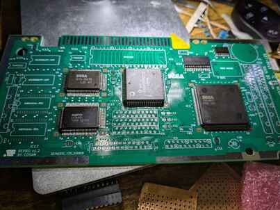
Anyways, with the QFP down, I started fitting the rest of the components.
I was out of some capacitors and ROM socket that I thought I still had in stock, so I couldn't complete the work last weekend, but I got most of it on:
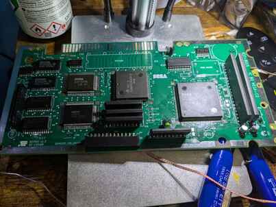
Yesterday I put the last bits on, which means it just needs an ultrasonic bath but is otherwise done!
I also added a slight mod for the save game chip, by installing a larger FRAM chip in place of the original SRAM, which does not need the battery to keep its data (Cypress rates it for 151 years of data retention after power off).
There's a mod where you run two extra address line pins to the 68k CPU, described on this page, which in tandem with a custom region-free BIOS allows full addressing of the chip's 32KB of memory without the use of bank switching.
That is a four times increase over the original 8KB, which usually gets filled up rather quickly.
So, the symptoms I was having on the previous board were that there was a persistent ticking sound, that coincided with stuttering on the BIOS splash screen music, alongside corrupted graphics at the BIOS splash screen (the MegaCD logo that shows off the rotational sprite manipulation was mostly invisible, sometimes showing corrupted bits of it), no life out of the CD drive, and a system hang the moment you'd go into the CD player interface.
There's some footage of that here, though I did not record the CD player interface hanging the system.
Well, what did I get on the first boot up of this board?
The good news, it's way better than before, as now the graphics corruption is complete gone, and the CD player interface now no longer hangs the system, as seen here.
The CD drive is still not showing signs of life, and the sound issue is still present.
But, for a first boot of a freshly populated-by-hand PCB with all sorts of fun SMD chips, I'm calling it a win either way!
I also haven't recapped the power board and CD drive yet, so I figured that would need to be addressed before moving on with any further diagnostics.
I was reading on the RetroSix Wiki that three 100uF capacitors on the power board in particular could cause "stuttering audio", though no sample was given of what that sounds like.
So just for a test, I recapped those three capacitors (not sure if I have the others on hand, if I had been more clever I'd have ordered those too...), which now results in a CD drive that's opening and closing the tray, and normal sound, but the video output has gone out (I checked and it's not the MegaDrive at fault).
I'm guessing with the CD drive now actually drawing power and operating to a certain degree, the rest of the crappy capacitors on the power board are strained harder, which might be causing the new problem, so I'm not too worried about is, especially as the recreated board wasn't messed with after the first power on test, soldering or components wise.
But I'm very happy with the current progress none the less 😀