VOGONS


Getting a MFM drive to run

Topic actions

Reply 20 of 35, by Matth79

User metadata
Rank Oldbie
Rank
Oldbie

The first one sounds like an ok ready-up, if the cable is bad, then the second one could be scrambled signalling

Reply 21 of 35, by Grzyb

User metadata
Rank l33t
Rank
l33t
wierd_w wrote on 2025-09-12, 13:06:

The cabling is done as 2 pairs. One long, one short, for each pair. I have labelled these with [1] and [2] respectively. The leftmost of each type is for HDD1, and the rightmost of each type is for HDD2.

Wrong!

Data cable connectors are separate for each of the drives.
Control cable connector is only one - in this case, there can be two HDDs on one control cable.
Some controllers even allow for four HDDs, all on one control cable.

The other 34-pin connector is for FDDs.

https://th99.infania.net/c/U-Z/21350.htm
https://theretroweb.com/expansioncards/s/unkn … disk-controller

Nie rzucim ziemi, skąd nasz root!

Reply 22 of 35, by Half-Saint

User metadata
Rank Oldbie
Rank
Oldbie
Grzyb wrote on 2025-09-12, 17:06:

Exactly this. The 34-pin connector on the far right was indeed connected to a 3,5" floppy disk drive.

I'll try to fix the cable this weekend and test the hard drive on Monday.

b15z33-2.png
f425xp-6.png

Reply 23 of 35, by wierd_w

User metadata
Rank Oldbie
Rank
Oldbie
Grzyb wrote on 2025-09-12, 17:06:
Wrong! […]
Show full quote
wierd_w wrote on 2025-09-12, 13:06:

The cabling is done as 2 pairs. One long, one short, for each pair. I have labelled these with [1] and [2] respectively. The leftmost of each type is for HDD1, and the rightmost of each type is for HDD2.

Wrong!

Data cable connectors are separate for each of the drives.
Control cable connector is only one - in this case, there can be two HDDs on one control cable.
Some controllers even allow for four HDDs, all on one control cable.

The other 34-pin connector is for FDDs.

https://th99.infania.net/c/U-Z/21350.htm
https://theretroweb.com/expansioncards/s/unkn … disk-controller

Herrp, yes!

(It *has* been more than 3 decades since i've used one of these cards!)

Thanks for the refresh. Needed the kick in the head, clearly!

Reply 24 of 35, by Half-Saint

User metadata
Rank Oldbie
Rank
Oldbie

Well, I cut off the destroyed part of the cable and moved the connector so fingers crossed, I'll report back about a working Mitsubishi hard drive on Monday 😀

b15z33-2.png
f425xp-6.png

Reply 25 of 35, by Half-Saint

User metadata
Rank Oldbie
Rank
Oldbie

I can report only partial success.

I tried a second hard drive (NEC D3142) with the same controller and it acted exactly the same. So this got me thinking that there must be something else wrong here.

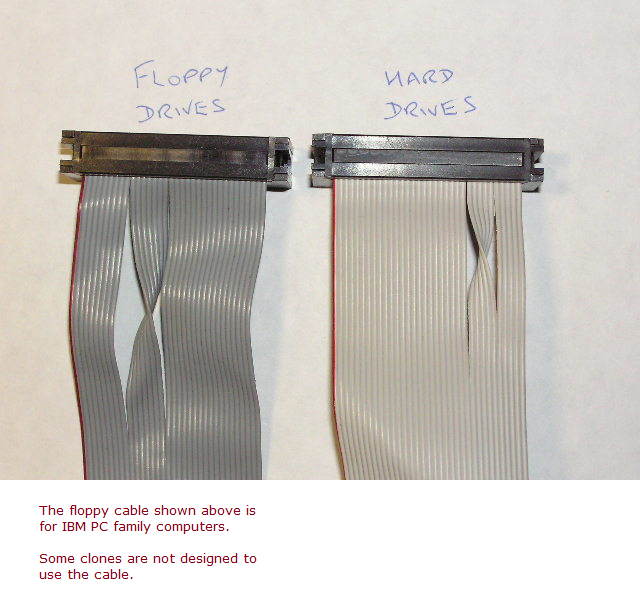
What I haven't tried yet is swapping the primary connector. This time, I connected the 2nd connector instead of the one at the end of the cable. There is no abnormal noise coming from the hard drive now and it passes the POST screen without reporting a C: hard drive failure. However, the computer now freezes at the 2nd screen when it should start booting into DOS.

Are there some other settings I should have set or changed? I'm testing this drive on a 386 motherboard. I haven't entered bad sectors from the label into BIOS.

With the NEC D3142, I don't get boot either but at least the computer doesn't freeze. It reports back drive A: not ready or something like that.

b15z33-2.png
f425xp-6.png

Reply 26 of 35, by Grzyb

User metadata
Rank l33t
Rank
l33t
Half-Saint wrote on Yesterday, 09:38:

This time, I connected the 2nd connector instead of the one at the end of the cable.

If you're installing a single HDD, it should be connected at the end of the control cable, and make sure the terminator is installed.
Is the control cable flat, or twisted?

Again, look at the diagrams - https://www.minuszerodegrees.net/5170/cards/5 … abling_info.htm

Also, general rules always apply - old connectors are naturally prone to oxydation/bad contact.
It often helps to remove all jumpers and install them again, toggle DIP-switches several times, and so on...

I haven't entered bad sectors from the label into BIOS.

You only have to enter them when doing Low Level Format.

Though you may be approaching the moment when it's time to give up on recovering the data, and do the LLF.
WIth MFM/RLL drives, the LLF is controller-specific - it's normal that a drive formatted with one controller won't work with another controller!

Nie rzucim ziemi, skąd nasz root!

Reply 27 of 35, by Half-Saint

User metadata
Rank Oldbie
Rank
Oldbie

Hey, thanks for giving me that link again. I only looked at it now and turns out I'm an idiot. I was using the floppy cable this whole time! Of course the correct cable has a cut in it and I need to relocate the connector before I can test it again.

I'm using the controller that was originally used with this hard drive so that shouldn't be an issue.

EDIT: I fixed the original cable (it's with a twist at the end) but it's still not working.

b15z33-2.png
f425xp-6.png

Reply 29 of 35, by Half-Saint

User metadata
Rank Oldbie
Rank
Oldbie

Yes, I tried DS2 and it freezes the system. The drive was set to D1 when I got it. Both the drive and controller were taken out of a system that was at one time being used.

To recap:
- parameters in BIOS are the following
Cylinders 977
Heads 5
Precomp 300
Landing Zone 0
Sectors 17
Total size 41MB
- using a 286 motherboard with ancient AMI BIOS from 1989
- hard drive connected to last connector with twisted cable
- DS2 selected
- rebuilt both Data and Control cables by cutting off the destroyed parts of cables and moving the connectors

Computer freezes when it should be starting DOS (see photo).

b15z33-2.png
f425xp-6.png

Reply 30 of 35, by st31276a

User metadata
Rank Member
Rank
Member
Half-Saint wrote on Today, 07:59:

- hard drive connected to last connector with twisted cable

Control cable should not have twist, the twist is for A: drive floppies.

Data cable should be on the data port that matches the DS of the drive.

With the 16 bit controller, the drive light comes on and stays on when the controller selects it. When you have two drives on the control cable, the currently selected drive's light is on. This is in contrast with XT controllers that flash the drive light when it is accessed. So if the light comes on and stays on, it is a good sign.

Does the computer also hang when you plug out the data cable? This might tell you if reads something that makes it hang, or something else makes it hang. Maybe wait a couple of minutes for something to time out.

Reply 31 of 35, by Half-Saint

User metadata
Rank Oldbie
Rank
Oldbie
st31276a wrote on Today, 08:38:
Control cable should not have twist, the twist is for A: drive floppies. […]
Show full quote
Half-Saint wrote on Today, 07:59:

- hard drive connected to last connector with twisted cable

Control cable should not have twist, the twist is for A: drive floppies.

Data cable should be on the data port that matches the DS of the drive.

With the 16 bit controller, the drive light comes on and stays on when the controller selects it. When you have two drives on the control cable, the currently selected drive's light is on. This is in contrast with XT controllers that flash the drive light when it is accessed. So if the light comes on and stays on, it is a good sign.

Does the computer also hang when you plug out the data cable? This might tell you if reads something that makes it hang, or something else makes it hang. Maybe wait a couple of minutes for something to time out.

My control cable has two edge connectors. The one at the end has the twist like in this picture: https://www.minuszerodegrees.net/misc/floppy_vs_hard.jpg

HDD LED comes on and stays on. You can see the FDD/HDD controller I'm using on the first page of the thread.

The computer freezes, Num Lock stays on and I can't reset the PC with CTRL-ALT-DEL. I haven't tried waiting for more than 5-10 seconds. Before the computer freezes, I can hear the HDD doing something. Is it reading data or not, I have no idea.

P.S. I found a 2nd control cable but it acts just the same as with the repaired one.

b15z33-2.png
f425xp-6.png

Reply 32 of 35, by Deunan

User metadata
Rank l33t
Rank
l33t

MFM cables can also be twisted but it's a different twist from what floppies have. Preferably connect that drive with 1:1 using straight section of the cable. Note that these HDDs also need a terminating resistor pack like early floppy drives, make sure it's present (though usually without it BIOS will detect controller/HDD issue).

Long wait/hang can be due to corrupted boot code in the first sector, but also invalid format that confuses the controller. Wait a few minutes or try booting from A: first and run LLF via debug.exe. Or perhaps if your BIOS has LLF option you can use that, usually works well with MFM and even some RLL controllers.

BTW Landing Zone 0 is a bad idea on real HDD, set it to 978 or 977 if the +1 doesn't seem to work properly. Docs say it's auto-parking HDD but I'm not familar with that model so better to set that LZ properly.

Reply 33 of 35, by st31276a

User metadata
Rank Member
Rank
Member

I see that strange twist before the last edge connector, looks like it swaps the DS lines around for hdd's.

I have only seen and used straight through control cables before, setting DS with jumpers on the drive itself.

The 20 pin ribbon does not use all its conductors, its basically +/- analogue read and write signals and loads of grounds iirc. Maybe the destroyed bit was unnecessary to begin with.

Reply 34 of 35, by Grzyb

User metadata
Rank l33t
Rank
l33t

Note that there's no need to enter all the parameters - AMI BIOS should already have these parameters as drive type 17.

You have tried both J2 and J3 data connectors, right?
The correct one seems to be J3, but such details sometimes get mistaken...

Anyway, at this point, I would simply take a working system, and started replacing the components, one by one...
If it's not possible - the only remaining thing is LLF...

Nie rzucim ziemi, skąd nasz root!

Reply 35 of 35, by Grzyb

User metadata
Rank l33t
Rank
l33t
wierd_w wrote on 2025-09-12, 13:06:

The cabling is done as 2 pairs. One long, one short, for each pair. I have labelled these with [1] and [2] respectively. The leftmost of each type is for HDD1, and the rightmost of each type is for HDD2.

I've just realized that you're not completely wrong with that statement...

See the following, from a Seagate disk manual:

JP7 Radial/Daisy-Chain Mode
----------------------------
x 1- 2 OPEN Daisy-Chain-Configuration
A Daisy-Chain configuration allows connection of
a maximum of two drives on a common control cable.
A separate data cable is required for each drive.
The last drive in the chain (physically farthest
from the controller) requires termination. All
other drives should not be terminated. The maximum
permitted cable length from the controller to
the last drive is 10ft (0.31m).
1- 2 CLOSE Radial Configuration
To configure the drive radially, install a jumper
on pins 1 and 2 of the user configuration jumper
block. If you configure the drive radially, leave
the resistor terminator packs installed on all
drives. Each radially connected drive has its own
control and data cable. Drives in this configuration
always remain selected.

However, controllers using Radial Configuration must be very rare - I haven't seen any yet.

Nie rzucim ziemi, skąd nasz root!