VOGONS


First post, by Omarkoman
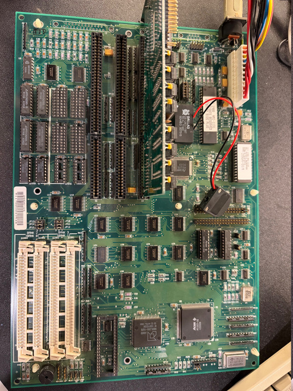
User metadata
Rank Member
Rank
Member

I got this board:

ECS 286A

https://theretroweb.com/motherboards/s/ecs-286a-2-0-2-1

photo of actual board - https://i.postimg.cc/4dhKFkv8/IMG-1593.jpg

its in immaculate condition.

upon researchig more about it, apparently I need to have the socket RAM chips populated at least in bank 0 in order to boot , without the chips it gives me 3 beeps. eg putting in 4 x 1MB sims in the slots and changing jumpers doesnt work. I

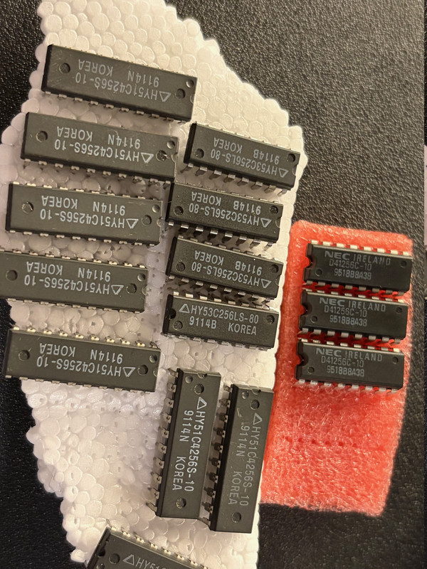
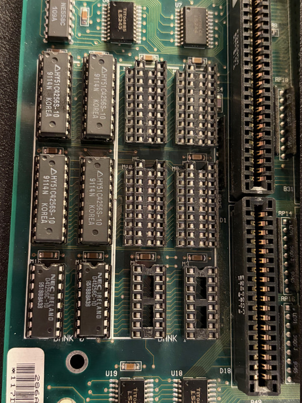
So I got these chips 44256 for RAM and 41256 for parity - (128kb capacity each so 512kb per bank plus parity same size):

https://i.postimg.cc/xdZJRTmd/IMG-1591.jpg

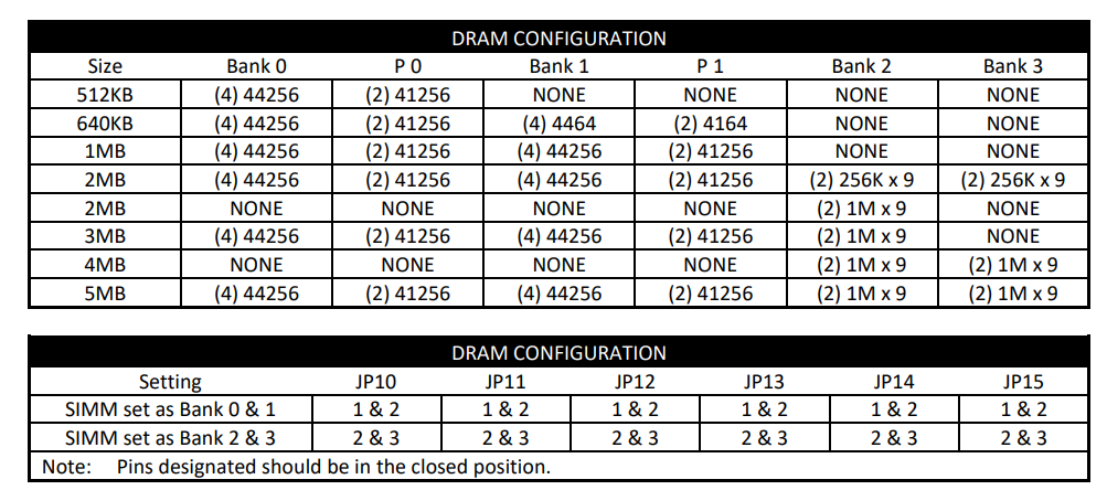
for bank 0 - 4 should be used for memory and 2 for parity - correct?

see motherboard manual on RAM config:

https://i.postimg.cc/fRh6Vxgk/board-ram-config.png

so once I put the chips in , jumpers JP10-JP15 are all on 1-2 setting .. see photo:

https://i.postimg.cc/63G71JVZ/IMG-1592.jpg

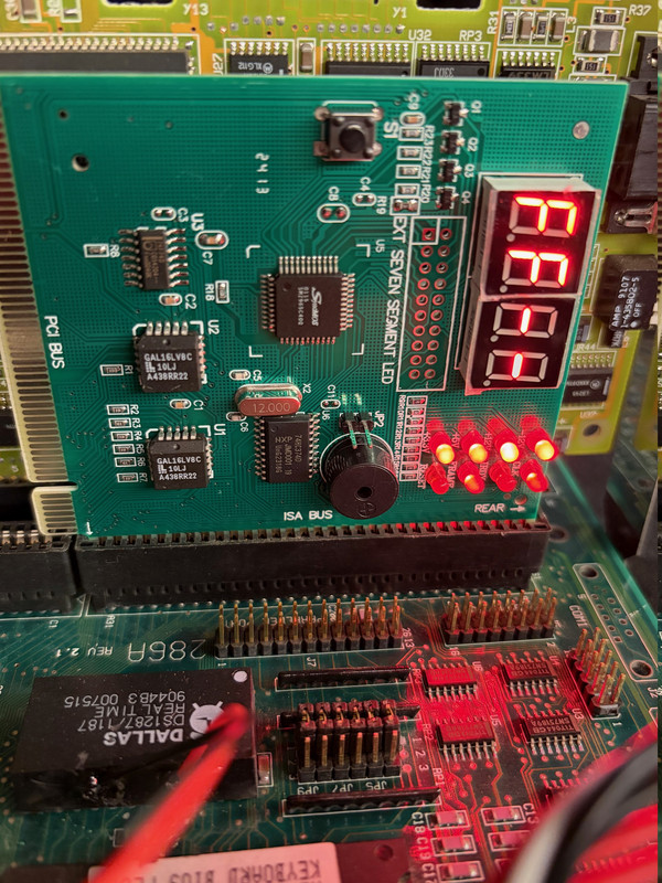
I no longer get 3 beeps but instead I get 2 long beeps and 8 short ones. Googling this, its apparently a video card issue ? is that right ?

I tried 5 different basic 16 bit ISA video cards in all 3 slots available and I get same beeps.

Any suggestions? Are there any other jumpers I need to jumper for the board ? Is this still RAM issue or some other problem?

PS leaving the socket ram chips slots empty and populating only the 4 SIMM slots with 1MB modules , or even 1 and selecting all jumpers to 2-3 it doesnt work and I get 3 beeps.

Reply 1 of 17, by wbahnassi

User metadata
Rank Oldbie
Rank
Oldbie

Yes, the new beeps are video issues. So at least you're past the memory issue now.

It could be that you need to adjust the Mono/Color jumper on the board.. It also could be an incompatible VGA card (I heard 286s can be picky).

Keep the VGA cable connected, sometimes the video error doesn't prevent the signal from showing up on the screen. But in case you don't get any picture, then try addressing any of the above.

If all fails, chances are you have an issue in the ISA slots.. a broken trace, dusty pins, touching pins ... make a visual inspection on all pins of all slots..

If nothing is apparent, you'll need to investigate with a multimeter and a scope.

Turbo XT 12MHz, 8-bit VGA, Dual 360K drives
Intel 386 DX-33, Speedstar 24X, SB 1.5, 1x CD
Intel 486 DX2-66, CL5428 VLB, SBPro 2, 2x CD
Intel Pentium 90, Matrox Millenium 2, SB16, 4x CD
HP Z400, Xeon 3.46GHz, YMF-744, Voodoo3, RTX2080Ti

Reply 2 of 17, by Omarkoman

User metadata
Rank Member
Rank
Member

Thaniks for the reply, the mono/color jumper is set to color. There really arent any other jumpers that should impact boot up options.

I looked over the board carefully and cant see any physical damage so its a mystery.

Will try few more ISA cards but I am running out of options.

Reply 3 of 17, by wbahnassi

User metadata
Rank Oldbie
Rank
Oldbie

Yeah I was afraid it didn't turn out something easy.
A few things that are still considered "easy":

* Try with an 8-bit display card. CGA/EGA (even if you don't connect it to any monitor), or even 8-bit VGA (but more rare). Also some 16-bit VGA cards do not mind running on the 8-bit slot. The point here is to tell whether the problem is in the 8-bit part of ISA or the 16-bit part. If you get display on the 8-bit slot then you know your problem is on one of the pins in the higher portion of the 16-bit slots.

* If you have one of those POST code analyzer cards, plug it in and see if it shows good lights or some missing ones (or if the reset signal is stuck on the ISA bus).

Outside of these two easy steps, I would have to continue with a multimeter and an oscilloscope. Measure clocks, look for activity on address and data pins, memory read/write pins... etc.

Turbo XT 12MHz, 8-bit VGA, Dual 360K drives
Intel 386 DX-33, Speedstar 24X, SB 1.5, 1x CD
Intel 486 DX2-66, CL5428 VLB, SBPro 2, 2x CD
Intel Pentium 90, Matrox Millenium 2, SB16, 4x CD
HP Z400, Xeon 3.46GHz, YMF-744, Voodoo3, RTX2080Ti

Reply 4 of 17, by BitWrangler

User metadata
Rank l33t++
Rank
l33t++

You can get a video fault on older, mostly pre 486 boards, when the VGA card doesn't presence detect the monitor, and throws a signal to the motherboard for that, which then faults for display and refuses to continue, jerk. This can happen on monitors too new to be aware of the old presence detect protocols, and that probably use digital presence detect.

Unicorn herding operations are proceeding, but all the totes of hens teeth and barrels of rocking horse poop give them plenty of hiding spots.

Reply 5 of 17, by Omarkoman

User metadata
Rank Member
Rank
Member

thanks for that I can try with a CRT, I normally just use an older LCD with VGA and havent had a single machine, including XTs that didnt show display on the LCD screen but definitely can try. This board though seems quite modern 286, not an early gen.

quick update, pluggin in a diagnostics card, the LCD screen on it shows FF, see photo:

https://i.postimg.cc/fTBHCgcW/IMG-1598.jpg

Also, I tried few more VERY old 16bit an done 8 bit VGA/EGA cards and still get the beeps. Then I tried an old monochrome card and there were no beeps at all but obviously I dont have a monochrome monitor to see if anything is displayed but there were no post beeps or anything like that either.

Reply 6 of 17, by Omarkoman

User metadata
Rank Member
Rank
Member

I think the fact I get two long beeps before the 8 short beeps is pointing to some other problem and not the video card ... its probably causing the video issue as a secondary problem.

what could the two long beeps mean ?

Reply 7 of 17, by st31276a

User metadata
Rank Member
Rank
Member

I think those beeps are particular to the init of a vga card, means display memory rw error if I remember right. Monochrome cards don’t have their own bios, their bios code is in the system rom - different init code runs when vga bios is not present.

If it gets to beeping like that it’s getting quite far, probably already passed the first 64k system memory test.

My guess is a signal integrity issue somewhere on the bus - touching pins, dodgy connections, etc.

Reply 8 of 17, by Omarkoman

User metadata
Rank Member
Rank
Member

I will spend more time on the board this weekend and do a more thorough visual inspection to see if I can identify anything broken, touching parts etc.

Reply 9 of 17, by Locutus

User metadata
Rank Member
Rank
Member
Omarkoman wrote on 2026-01-13, 00:16:

quick update, pluggin in a diagnostics card, the LCD screen on it shows FF, see photo:
https://i.postimg.cc/fTBHCgcW/IMG-1598.jpg

Hi.
Grab a scope and check the ISA D0–D7 lines.
They’re usually pulled up to +5 V with ~10 k resistors.
Seeing FFh (11111111) might mean that nothing is driving them / hardly pulling them up ?

Reply 10 of 17, by Omarkoman

User metadata
Rank Member
Rank
Member

unfortunately I dont have a scope you refer and am fairly inexperienced when it comes to actual electronics hardware repair. I'll start with visual inspection first and see what I find.

Reply 11 of 17, by BitWrangler

User metadata
Rank l33t++
Rank
l33t++

Don't forget your fingertips, anything suspiciously hot or suspiciously cold.

Unicorn herding operations are proceeding, but all the totes of hens teeth and barrels of rocking horse poop give them plenty of hiding spots.

Reply 12 of 17, by Omarkoman

User metadata
Rank Member
Rank
Member

good point thanks ! I have a thermal camera so will run it over the board!

Reply 13 of 17, by st31276a

User metadata
Rank Member
Rank
Member

My suspicion if the VGA bios manages to run and generate beeps, is that at least D0-D7 are probably fine. I suspect an address line.

Reply 14 of 17, by Locutus

User metadata
Rank Member
Rank
Member
Omarkoman wrote on 2026-01-14, 01:38:

unfortunately I dont have a scope you refer and am fairly inexperienced when it comes to actual electronics hardware repair. I'll start with visual inspection first and see what I find.

If the visual inspection does not reveal any relevant issues, measure the resistance of the ISA data and address lines to GND and +5 V

Reply 15 of 17, by Omarkoman

User metadata
Rank Member
Rank
Member

I spent good 5 mins looking under bright light with magnifying glass and cant see any physical damage on this board, its in excellent condition.

regarding this: measure the resistance of the ISA data and address lines to GND and +5 V

where exactly am I measuring, which ISA data and address lines ... sorry can you pls be more specific or show in a picture what parts am I touching using a multimeter?

Thank you.

Reply 16 of 17, by st31276a

User metadata
Rank Member
Rank
Member

Easiest way would be from a power or ground pin on the P8/P9 AT power connection to the copper contacts in an ISA slot. If you image search for ISA slot pinout there might pop something up that is easy to compare to when measuring.

Reply 17 of 17, by Omarkoman

User metadata
Rank Member
Rank
Member

Thanks all but I think the measuring part is beyond my capability for now, I will have ot put this board away until I have time to educate myself further on this type of testing. Im not giving up on this board yet.