VOGONS


First post, by geordiepingu

User metadata
Rank Newbie
Rank
Newbie

One of my occasional hobbies is restoring vintage electronics, mostly computers. What I do with them after I’ve mended them all completely depends. If it’s interesting to me and I’ve got the space, I will keep it. Otherwise, I will usually sell them or gift them to friends who would enjoy some of these bits of kit.

This motherboard – the MSI K7D Master – was of particular curiosity in my youth and quite frankly, classed as unobtanium at the time: dual-socket or dual-processor machines. Windows NT, 2000, and XP could take advantage of these configurations at the time, whether or not the underlying software you were running could was another matter. However, these were multitasking powerhouses back in the day, but they probably wouldn’t do anything to make my retro games faster!

That said, I think dual socket boards are cool (in retro geek terms) and great platforms for some of my nostalgic games. The K7D Master features an AGP slot and a good amount of expansion for sound cards, fast storage, etc.

Like any old contraption, this board needed a bit of TLC to work properly. Components fail with age, and things get damaged as they get handled.

The MSI K7D Master-L is a fairly early SMP Athlon board, sporting 2x 462-pin CPU sockets (socket A/462) and an AMD 760MPX chipset. This enables the board to do some rudimentary overclocking of some Athlon MPs or modified XPs, which is pretty rare for an SMP motherboard, typically speaking. Given I was overclocking Pentium 2s, 3s, 4s, and Athlons in my youth, you can see the appeal. Further to this, the board features an AGP Pro slot, 2x PCI-X 64-bit slots, and 3x PCI slots. As standard, it has 2x IDE controllers, a game port, AC97 audio, Intel 100Mb Pro Ethernet, a couple of USB ports, and PS/2 ports to boot. In summary, it has SMP support, can do some (very basic) overclocking, and plenty of connectivity and expansion.

I got my board for free from my friend Emma, who was downsizing, which came with a pair of Athlon 2000+ MPs. It worked, but had a few niggles. Retro game installers would throw CRC errors – despite different HDDs and RAM configurations, the Intel NIC wouldn’t negotiate a connection properly, and sometimes the machine would just refuse to boot at all. My gut instinct told me there would be some electrical gremlins on the board that need attending to.

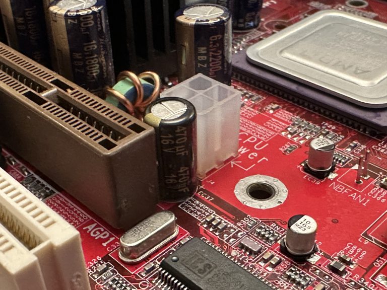
The capacitors, on a first glance, looked OK. There was a mix of Rubycons (awesome) and some Teapo (Taiwanese) capacitors. There were no obvious signs of bulging. A further, closer look with my glasses on had me noticing some goop under the capacitors. On some boards, this can be a glue used in the manufacturing process to keep capacitors in place. However, this was not consistent, so I thought I might as well buy caps for the entire board.

I then took a third look at the SMD components on the board. Some of them were clearly missing!
IMG_1435-768x1024.jpeg

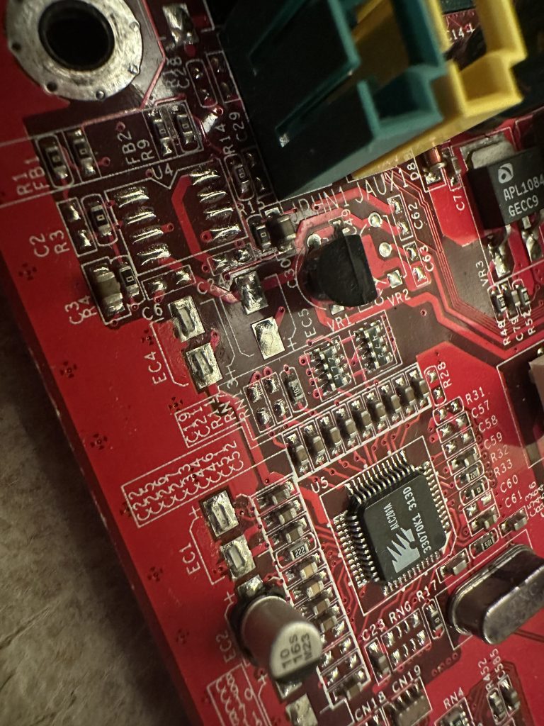
That added to my list of components for the board. I used some high-resolution photographs from The Retro Web to verify what was missing, as I didn’t have schematics.

I ordered my components from a mix of RS components and CPC Farnell. CPC Farnell is my first go-to as they are less than a 30-minute drive from me if I need something quickly. It is worth noting that the Teapo capacitors have an 8mm footprint, which can be difficult to find. This footprint must be observed, as these capacitors are bunched together very tightly. Anything larger won’t fit properly and will look untidy, and won’t be mounted in a stable manner to the board. Anywhere else, I ensure the leg pitch is the same where possible.

I also make an effort to find components that have a similar ESR and are from a reputable manufacturer. Rubycon, Chemicon, Panasonic, etc, are my go-to here.

The shopping list for those who are following along at home or recapping a similar board:

Rubycon 16ML100MEFC6.3X7
Panasonic EEUFM1C471L
Panasonic EEUFM0J222L
Chemi-con EKY-6R3ELL102MH15D
Rubycon 16ZLH1800MEFC10X23
Panasonic EEEFK1C100AR
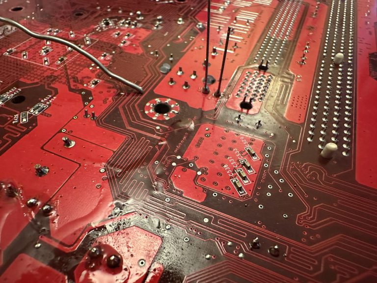
I started trying to desolder some of the suspect caps, the key here being trying. The K7D’s ground planes are big and contain a lot of copper; it was going to be a huge effort to heat. I could pre-heat the board, but I had also lost my big soldering iron. Regardless of preheating, it was taking my small 18w iron far too long, and I didn’t want to risk damaging the board. Long gone was my proper soldering station. This sounded like a good excuse to browse CPC’s catalogue…

I ended up finding a Weller 85W soldering station that was significantly cheaper than the usual suspects online, so I jumped in the car and picked it up without hesitation. I haven’t used a station in the last few years of repairing retro electronics, and I had forgotten how much easier it made this process! So much so, I decided to start replacing some more of the Teapo Taiwanese capacitors so my inner snob could be satisfied.

IMG_1460-768x1024.jpeg
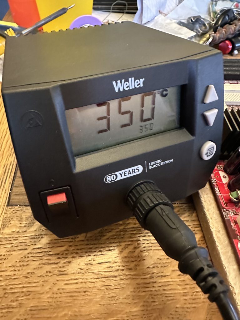
The Weller is very easy to use and very responsive to heat demands. I managed to get away with doing the rest of the repairs without preheating the board.

IMG_1486-768x1024.jpeg
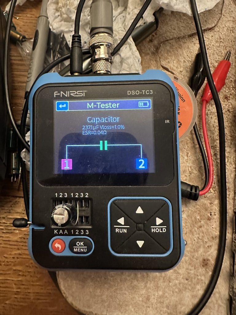
My process involves testing each capacitor before installation to reduce the risk of installing defective capacitors. This multifunction oscilloscope, which I primarily use for testing electronic fuel injection sensors, also has a capacitor and circuit tester built in. Quite handy!

IMG_1463-768x576.jpeg
IMG_1474-768x576.jpeg
IMG_1472-768x576.jpeg
IMG_1477-768x1024.jpeg
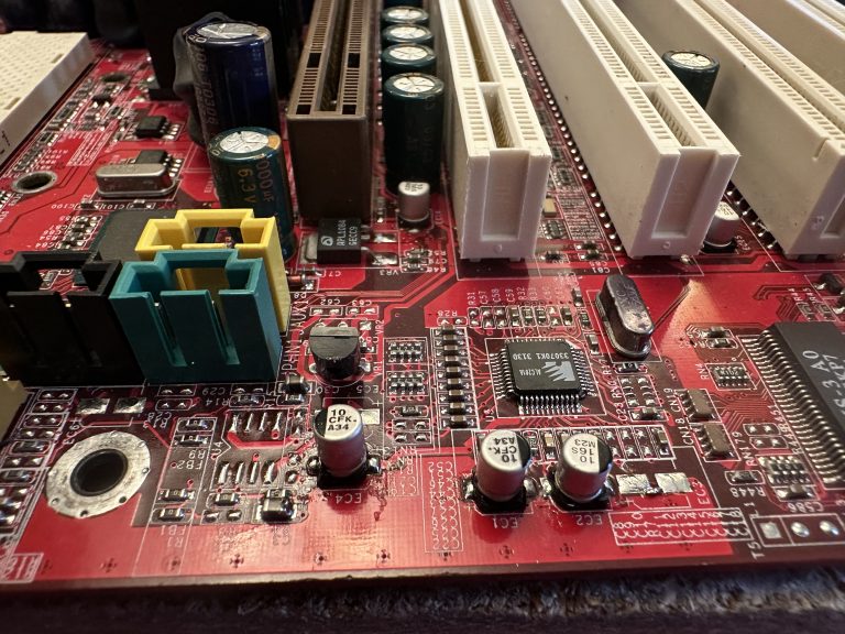
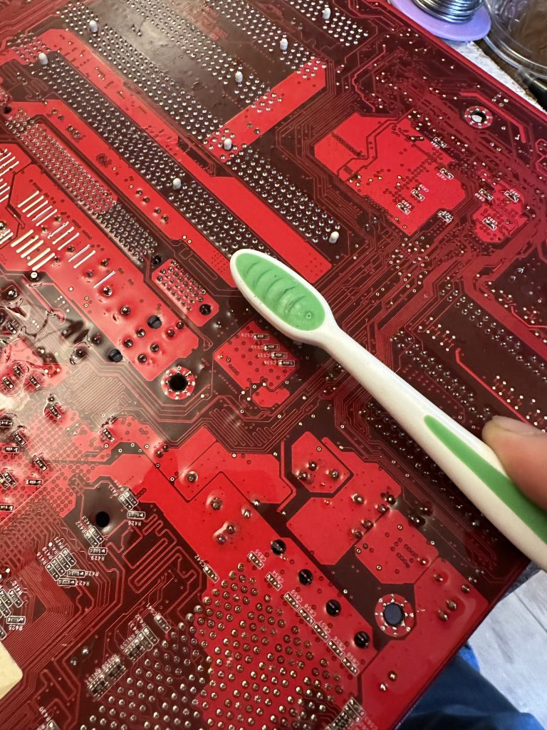
Once I soldered the capacitors in, I got a tin of isopropanol out and started using a clean toothbrush to scrub the work area and eradicate any flux on the motherboard.

The next stage was to build the system up with components I had in my spares box. This is built up of a mix of stuff I’ve had for over 20 years, with stuff I’ve recycled from other computers over the years, acquired when I’ve found a good deal, or been given by friends. To put a long story short, I decided to go overkill so I could really see what the Athlon MP platform could do.

Overall Specifications:

Dual AMD Athlon MP 2000+
2GB DDR 3200 RAM
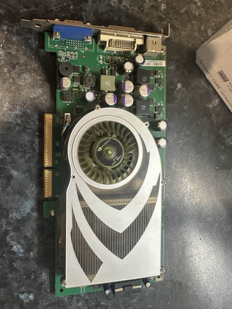
Nvidia GeForce 7800GS AGP 256MB
MSI K7D Master L
Toshiba Q Series 128GB SSD SATA
Seagate 2TB 7200RPM HDD SATA
2x Hitachi Deskstar 250GB 7200RPM ATA/IDE
Promise TX4 SATA controller
Asus Xonar DS Sound Card
NZXT C750 Power Supply
Chieftec Dragon ATX Full Tower Case
Arctic 80mm fans for the case
3.5″ Sony Floppy Drive
3.5″ Gotek Floppy Emulator
Pioneer DVR-107 DVD-RW ATA Writer
HL DVD-RW DL SATA Writer

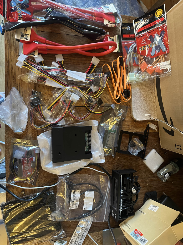
To make the build happen, I used a mix of new-old stock cables and splitters off eBay, and some interesting bits from Aliexpress. E.g. the Gotek floppy emulator and a “Bay Filler” Fan controller. Having Newlink round ATA/IDE cables really did make me feel like I was taking a PC apart in 2003 all over again.

image-768x1024.png
And strangely enough, this Nvidia GeForce 7800GS AGP was advertised at an absolutely bargain price on Aliexpress at the time of buying. Turns out it’s for a later SEGA arcade cabinet, or my Windows XP Athlon MP Rig… Some new Noctua thermal paste and the card is merrily on its way into the rig.
image-2-768x1024.png

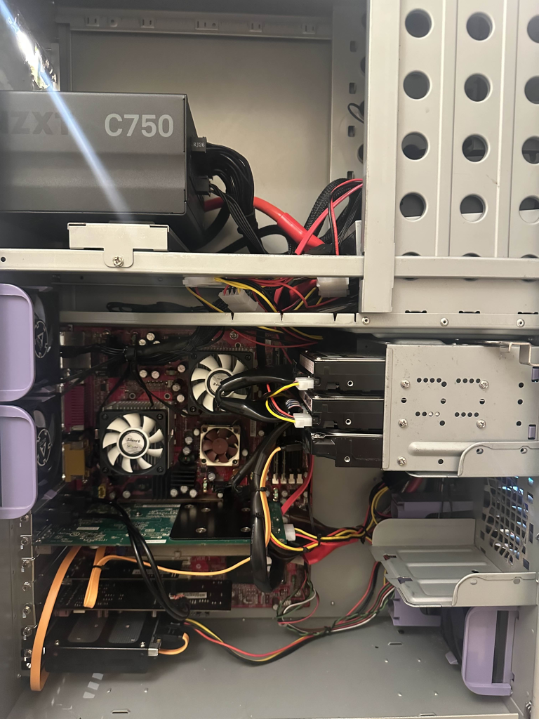
Assembled inside, with some rudimentary, but probably period-correct cable management.
image-5-768x1024.png

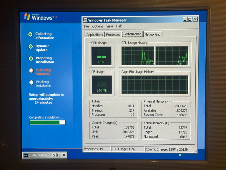
Next came a clean installation of Windows XP Professional, now that I had picked and installed the hardware I was going to run in the system.
image-7-768x576.png

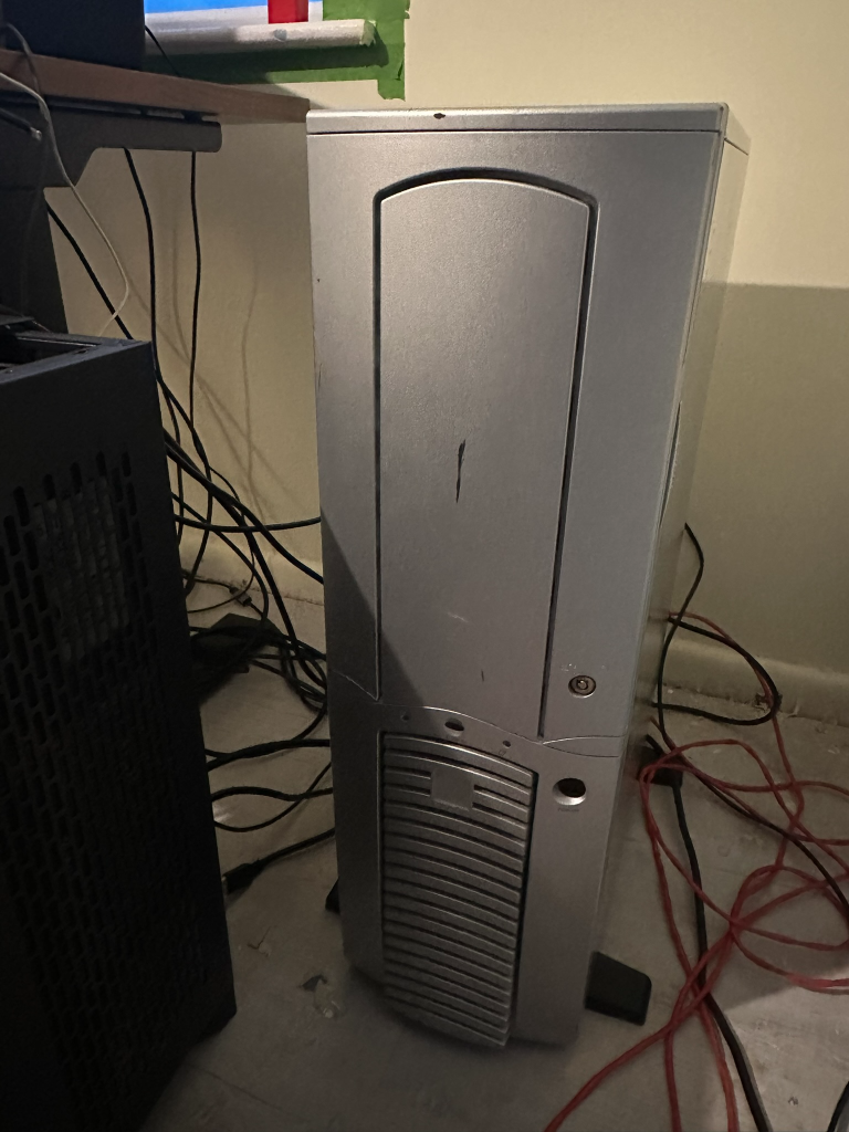
The finished article currently looks like this. Pardon the mess as I am midway through re-decorating my office.
image-8-768x1024.png
image-9-768x1024.png

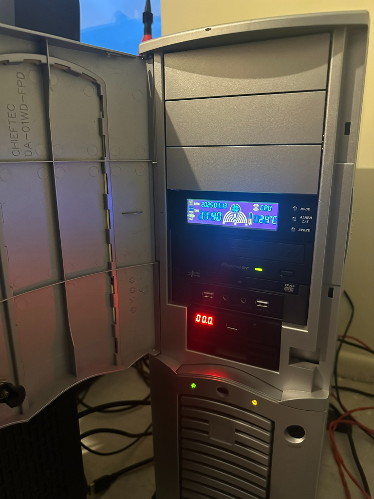
Overall, the project has been a success, with the only real outlay being a strange Aliexpress card, a Chieftec Dragon I found for buttons on Facebook Marketplace on the way back from work, and some nostalgia-trip ATA cables. The machine currently runs NFS Most Wanted without a problem. I’m yet to spend the time to install my other retro games – at some point, it will happen, I am sure.

The next salute as some may have seen on reddit, is to finish the KVM setup so I can keep this machine and some others in my office.

Reply 1 of 18, by geordiepingu

User metadata
Rank Newbie
Rank
Newbie

Having been invited to "Come Play" in the Socket 462 OC thread here, I have decided that I ought to actually try some overclocking. Unfortunately, having a 133MHz FSB with AGP and PCI multipliers tied to it is causing me issues getting past Dual 2100s, even with a load of volts and with a different graphics card (X800 GTO). Maybe my SATA card isn't helping, so I may try doing a "benchmarking only" install of XP on one of the IDE HDDs.

So, as my luck would have it, I've managed to find 2x XP 2500+ Bartons that are unlocked on eBay, which ought to help, as I will have twice the cache of my Palominos. My plan here is to do the L5 bridge mod somehow to get the two CPUs identifying as MPs (any advice appreciated!!) and then pin-mod the multiplier, FSB, and voltage to see about getting these guys into the 3000 realm, if I can dissipate the heat. I have some other CPUs to practice the L5 bridge mod on; however, I have struggled so far on the green CPUs. My guess is the pins must have some conformal coating or lacquer on them that I haven't tried scraping yet? I'd like to avoid getting into the realm of microsoldering, or if I must, find someone in the UK that can do the mod for me.

On the heat note, I've identified some water blocks I can modify to work with the through-hole mounting solution on the board if the worst comes to worst, although I am trying to come to terms with spending that much on an old rig, as a Northerner (English people will get the joke).

Obviously an Athlon 2500+ is only a 2500+, but to find two that are unlocked, with the same stepping, is almost unheard of. The other is still shipping at the moment, so fingers crossed it arrives in tact.

file.php?mode=view&id=243375

Reply 2 of 18, by shevalier

User metadata
Rank Oldbie
Rank
Oldbie

The paw-shaped feet on Chieftec cases certainly look very original.
However, because of this design, the cases themselves rattle and vibrate.

I highly recommend replacing them with standard rubber or silicone feet from your nearest furniture shop.

And as for ASUS sound cards (all of them).
These are HBAs – Host-Based Adapters – i.e. entirely software-based devices, with all their functionality executed on the CPU.
Despite the fact that they signal to the operating system that they are ‘EAX-compatible’ and so on, they do not actually have such functionality; it is simply a software workaround to prevent games from crashing. For the era around Windows XP, well, it’s certainly not the best option.

Aopen MX3S, PIII-S Tualatin 1133, Radeon 9800Pro@XT BIOS, Audigy 4 SB0610
JetWay K8T8AS, Athlon DH-E6 3000+, Radeon HD2600Pro AGP, Audigy 2 Value SB0400
Gigabyte Ga-k8n51gmf, Turion64 ML-30@2.2GHz , Radeon X800GTO PL16, Diamond monster sound MX300

Reply 3 of 18, by geordiepingu

User metadata
Rank Newbie
Rank
Newbie

Would you recommend I invest in an XFI or just stick with my Audigy 2 ZS that's in another system at the moment?

Reply 4 of 18, by shevalier

User metadata
Rank Oldbie
Rank
Oldbie
geordiepingu wrote on 2026-06-03, 12:22:

Would you recommend I invest in an XFI or just stick with my Audigy 2 ZS that's in another system at the moment?

If your have for other system an another decent sound card, the Audigy 2ZS is an excellent choice.

If not, any card from the X-Fi series that connects via a PCI bus will do. However, you won’t be able to use it with Windows 98; it only works with XP.
Naturally, the X-Fi with the EMU20k1 chip, not the X-Fi Xtreme Audio

Aopen MX3S, PIII-S Tualatin 1133, Radeon 9800Pro@XT BIOS, Audigy 4 SB0610
JetWay K8T8AS, Athlon DH-E6 3000+, Radeon HD2600Pro AGP, Audigy 2 Value SB0400
Gigabyte Ga-k8n51gmf, Turion64 ML-30@2.2GHz , Radeon X800GTO PL16, Diamond monster sound MX300

Reply 5 of 18, by geordiepingu

User metadata
Rank Newbie
Rank
Newbie

To reflect the testing and tweaking going on in the Shoot for the Stars thread: Socket A: Aiming for the Stars!!!

I've temporarily fitted an old Audigy in place of the Xonar DS and installed some "desperation fans" to cool the overclocked system.
file.php?mode=view&id=243512

After much ferkling, I have the system stable with a small overclock. The settings here are more for my reference as I keep trying to push the system over time. Definitely struggling to push the Palominos; I really do need the other Barton to arrive and start modding it.

140MHz FSB, 1750MHz CPUs @1.8v
455MHz GPU OC, 1305MHz VRAM OC
Memory at 2-3-3-6 (2x1GB PC3200 Unbuffered @ 140MHz)
AGP Sec Lat Timer: 40h
PCI Latency Timer: 64
Aperture Size: 256MB

So far the benchmarks:
3DMark 2001SE: 10354
SuperPi 1.5 XS 1M: 1m 10.125s
CPUMark99: 146
Cinebench 2003 Single: 217
Cinebench 2003 Multi: 402

Reply 6 of 18, by shevalier

User metadata
Rank Oldbie
Rank
Oldbie
geordiepingu wrote on 2026-06-04, 10:29:

To reflect the testing and tweaking going on in the Shoot for the Stars thread: Socket A: Aiming for the Stars!!!

I’m afraid there’s not much to be gained from the motherboard’s dual-core CPU in this test.
The second core will always be at a disadvantage in single-threaded applications, and the test suite is very typical of high-frequency single-core CPUs.

All records for a specific graphics card in 3DMark 2001SE are set using a single-core processor running at the highest possible clock speed (or a multi-core processor with some cores disabled)
For AGP, this is a Phenom 2 or Core 2 Duo with clock speeds around of 4 GHz.
This test does not distinguish between CPU and GPU performance, reducing everything to a single overall score.
It’s a well-known and rather unpleasant thing, really.

Aopen MX3S, PIII-S Tualatin 1133, Radeon 9800Pro@XT BIOS, Audigy 4 SB0610
JetWay K8T8AS, Athlon DH-E6 3000+, Radeon HD2600Pro AGP, Audigy 2 Value SB0400
Gigabyte Ga-k8n51gmf, Turion64 ML-30@2.2GHz , Radeon X800GTO PL16, Diamond monster sound MX300

Reply 7 of 18, by geordiepingu

User metadata
Rank Newbie
Rank
Newbie
shevalier wrote on 2026-06-04, 16:39:
I’m afraid there’s not much to be gained from the motherboard’s dual-core CPU in this test. The second core will always be at a […]
Show full quote
geordiepingu wrote on 2026-06-04, 10:29:

To reflect the testing and tweaking going on in the Shoot for the Stars thread: Socket A: Aiming for the Stars!!!

I’m afraid there’s not much to be gained from the motherboard’s dual-core CPU in this test.
The second core will always be at a disadvantage in single-threaded applications, and the test suite is very typical of high-frequency single-core CPUs.

All records for a specific graphics card in 3DMark 2001SE are set using a single-core processor running at the highest possible clock speed (or a multi-core processor with some cores disabled)
For AGP, this is a Phenom 2 or Core 2 Duo with clock speeds around of 4 GHz.
This test does not distinguish between CPU and GPU performance, reducing everything to a single overall score.
It’s a well-known and rather unpleasant thing, really.

Fully aware of that, it is more about getting the most out of this platform than going for gold on 462, otherwise I’d have sold this, profited, and bought an nforce based motherboard. I did gently suggest that Cinebench 2003 is a useful test for dual CPU entries, so we will see if that starts to get a leaderboard.

Reply 8 of 18, by geordiepingu

User metadata
Rank Newbie
Rank
Newbie

Having looked through one of my PC component boxes, I couldn't find my Audigy 2 ZS, so can only think it's in one of my lock-ups, if I even still have it.

However, I did spot, on eBay, an X-FI Xtreme Music SB0460 for less than the price of most Audigy 2s. So I did a buy.

I've now done an install. Just waiting for the SB Link adapter to arrive so I can plug in the front panel audio (I hate having loose connectors flying around). I had a quick game of San Andreas on the system this morning, and it seems to be working fine.

In other news, I now have both Barton 2500+s. AXDA2500K4VDs. AQXEA stepping (not the best but not the worst). Both are week 34 or older, so not superlocked. I have just bought a 3rd for insurance, as I know how hard it is to find two that match, especially given the risk I am taking by modifying them. At some point in the very near future, I will attempt to perform the L5 bridge mod on the ones I have, using some conformal coating and conductive paint. If I can make both work and boot up at the very least, I will then explore socket/pin modding to get the clocks I really want out of them.

Reply 9 of 18, by geordiepingu

User metadata
Rank Newbie
Rank
Newbie

So... 50/50 success so far with the L5 bridge mod on the Bartons at hand. The great news is I've not killed any CPUs so far.

My method has been to use an overcoat pen to fill in the laser-cut gaps, use a combination of flux, solder, and a pin to make sure the bridge pins are conductive, then use silver conductive paint (and cure at 150c in the oven for 5 mins) to make the connection.

The green PCB CPU works fine and identifies as an MP. The brown one identifies as an XP. I suspect the brown one is not actually the L5 bridge pin and has it hidden under some solder mask.

I'll leave the brown one in a dish of isopropyl to help clean the stuff off. The other CPU on the way is a green one, which was easier to modify.

Reply 10 of 18, by geordiepingu

User metadata
Rank Newbie
Rank
Newbie

If at first you don't succeed, try again. I tried rubbing a steel pin against the solder mask, and managed to get 2x Bartons booting as MPs. At 12.5x140 I am still running at 1750MHz which is to be expected. Unfortunately, I've been a bit too hamfisted with the 2nd CPU and bent one of the pins in quite a way I've never managed before, so some great care has to be taken inserting and removing the CPU. Next will be to modify the sockets to try and shift the multiplier up (add x8), as the motherboard electrically tops out at 12.5.

Moving to Bartons alone has moved my 3DMark score to 11013, which I will credit to increasing the L2 cache of each CPU to 512KB. Onwards and upwards!
file.php?mode=view&id=244094

Reply 11 of 18, by geordiepingu

User metadata
Rank Newbie
Rank
Newbie

Done some tweaking, because it's never enough.... Learned a few things in the process.

1. FSB is at 150MHz.
2. Memory Timings are 2-2-2-5
3. PCI Latency Timer set back to 32
4. AGP Secondary Lat Timer still at 40h
5. STOCK VOLTAGES! (1.6v)

PC runs, posts, plays, works reliably. Bartons running at 12.5x150 = 1875MHz. This is starting to put some of the other Barton scores in my iron sights now, which is good news. Now I am trying to work out if I was somehow hitting a limit of the CPU, or if I was just consuming so much power that I was causing the rest of the board to destabilise. Either way, considering this is a workstation board with a shared memory controller where I will never win on memory bandwidth or latency, I'm really happy where I've gotten to today.

3DMark01 SE: 13968
Cinebench Single: 233
Cinebench Multi: 435
CPUMark99: 165
SuperPi 1.5 1M: 1m 1.438s

Really quite impressed that before socket modding I've started to get towards the 14k territory. It is also unbelievable how much faster the system generally is - likely due to the fact I've got much better memory latency now.

Reply 12 of 18, by geordiepingu

User metadata
Rank Newbie
Rank
Newbie

The more and more I think about what I'm trying to do with the system, the more and more I think about sympathetically modding it...

Here's my line of thinking: I'm contemplating watercooling the system by modifying some COTS waterblocks and also making some socket cutouts on the motherboard tray, so I can do the socket pin mods from behind the board.

I wanted to avoid cutting the Chieftec Dragon initially; however, the more I think about it, the more I convince myself it's reversible. It's in a non-visible location, and I can always weld, grind, and paint it back (I can MIG and TIG weld at home). Having the cutouts on the back of the motherboard tray will reduce the risk of me trashing what are now practically unobtanium CPUs while reinserting CPUs during the socket mod to raise the multiplier, either via cracking the die or trashing more pins. So, I may get my plasma cutter and dremel out.

The next thought is I am really struggling to find good coolers, and I am unfortunately unlikely to find CPUs with a cooler stepping. At the moment, my thermal headroom is not great for overclocking the CPUs. As an interim measure, I will install some fans on the CPU coolers with higher static pressure (just bought some Noctua NF-A6x25s), at the expense of noise, and see what that does. Longer term, I have watercooling in mind, as being in the UK means I am really unlikely to find 2x appropriate coolers that fit. FWIW, I currently have 2x Startech coolers that seem to just be aluminium, with Gelid 60mm fans on (I know not the best).

So, the exam question. What can I modify that is COTS, that is probably "good enough" and feasible? I am _that guy_ that modified Chinese 939 blocks years ago to pointlessly watercool two Pentium 2s in a 4U industrial rack chassis for "fun", although the images are lost to the sands of time with Imgur now.

Looking at these waterblocks https://www.ebay.co.uk/itm/358550422439
file.php?mode=view&id=244325
My gut and quick head maths says I can modify and cut the bracket to fit the 4 holes around the socket. I may have to adjust the position to avoid the "bump" in the socket, or use a thicker copper shim. However, there are no caps around the socket that would obstruct the area. Spring retainers on the hardware will also help reduce the risk of cracking dies.

Now then, may as well watercool the northbridge while I'm at it?
file.php?mode=view&id=244326
The slidey brackets look like they will work with the existing push pins on the K7D fan-powered northbridge cooler.

I'm not such a monster that I would cut up side panels or hack the sides of the case for radiators. However, I've got some conflicting food for thought...

There is a large cavity above the PSU, where a second PSU would go. I am also willing to modify that dual PSU bracket, as it is removable and I could easily draw up the pattern to remake it before I cut it. Directly mounted, I could get a single 80mm radiator on there easily. With a bit more finesse and time, I could make a steel bracket that mounts a dual 120mm radiator, open up the PSU bay as much as I can, and make an air duct out of fibreglass or even 3D printed to fit. It will not be quiet as I anticipate there'd be a fair amount of turbulence with the intake being so close to the side of the case.
I could probably fit a dual 80mm radiator where the rear fans are.
I could also fit a single 80mm radiator in the front, although I'd rather that was bringing in cool air so I can feed some fans that I would place on the VRMs, and for the GPU.
I'm not a fan of external radiators unless I find a cracking deal on one of those old Zalman towers in good nick, as tempting as it is to stick the radiator in the refrigerator. I haven't really got room for an external solution (unless it's cool enough to make room for).

If I still have thermal headroom (i.e. can get enough radiator square footage), then why not go all out ridiculous and watercool the GPU? 2x blocks - one for the PCI-E to AGP bridge and some small heatsinks for both the VRMs and VRAM chips (the VRMs currently are not cooled by anything other than ambient air!).

What about the res and pump?! These things come up from time to time, but nothing is stopping me from getting an Alphacool unit and running the pump separately at the bottom of the case, if I can't find one. https://www.xs-pc.com/discontinued-eol/acryli … ir-for-laing-d5

Have I lost the plot?!

Reply 13 of 18, by chrismeyer6

User metadata
Rank l33t
Rank
l33t

I love the idea to water cool the two CPUs and North Bridge as I'm a sucker for a custom loop. Instead of trying to modify the case to fit the rads. Why don't you build a radiator box to sit next to the PC? You can run the lines out the back and use a fan extender and a hub in the rad box and just run the wire back to the motherboard with the coolant lines. Just a thought I had reading your post.

Reply 14 of 18, by cyclone3d

User metadata
Rank l33t++
Rank
l33t++

The other option is to add the radiator to the top of the case. My main desktop at home is in a Loan Li case that had mounting holes for up to a 360 radiator, but I wanted a 420 radiator so I made a template and cut out new holes with my dremel tool and cutoff disks.

The radiator is a super thick all copper radiator with a push/pull fab setup using insanely powerful fans that are set to run as low speed as possible under idle.

I'll probably end up using this setup, except for the water block for every build going forward.

By doing a setup like this, it gives better cooling for everything as all the "hot" air is exhausted out the top of the case. Plus it is super cool to have a giant radiator mounted to the outside of the top of the case.

Yamaha modified setupds and drivers
Yamaha XG repository
YMF7x4 Guide
Aopen AW744L II SB-LINK

Reply 15 of 18, by geordiepingu

User metadata
Rank Newbie
Rank
Newbie

You both have points that inspire a couple of thoughts...

I'm still hesitant to do any external cuts to the chassis, although I did think of a compromise. The side panel. A lot of dragons had acrylic sides; mine does not. Not a lot of dragons around seem to be dual-PSU variants; mine is.
With that logic, I would absolutely consider cutting the side panel to fit an acrylic cover. I could mount a 240mm radiator to the top of it having just measured, sideways, with some long enough tubes on quick disconnects, exhausting out of the case. That would give me some of the advantage of getting the ambient hot air out of the case. It would also mean that I get to show off the innards of such a rare rig...

I have also just seen this gent's idea of sitting the rad on top of the computer https://www.toddkumpf.com/index.php?id=amd_quad_fx
With the above, I could use the spare PSU cutout to route the hoses. I would just want to do something with the radiator to not make it seem such a haphazard positioning. Perhaps I could go about fabricating some sort of "enclosure", with fan filters, as I have ragdoll cats........

Still torn with your idea of putting roof mounts in @cyclone3d. 240mm is quite easy and still allows for use of the top bay; I just worry about it looking strange with the dragon's proportions and me regretting it.

There is also the fact that I might just need to get over myself and mod the case. It has scratches and could do with a paint job anyway. It's not a perfect preservation of an original case and was the go-to for modders anyway.... Or am I just telling myself that?

Reply 16 of 18, by geordiepingu

User metadata
Rank Newbie
Rank
Newbie

So, to prove the theory that my little StarTech heatsinks won't do much more, I threw some Noctua 60x25mm fans on. Sure enough, 1c in temperature, if that.

file.php?mode=view&id=244536

I did also do this the other day - although it will take a bit longer than planned, as I have another expensive engine bill
file.php?mode=view&id=244537

My current thinking is to use one of these Barrow EXWCD-240 radboxes. They don't look offensive, and I could locate them out onto a shelf. Unsure on 1 or 2 rads yet.
https://www.ldlc.com/en/product/PB00495944.html

Reply 17 of 18, by geordiepingu

User metadata
Rank Newbie
Rank
Newbie

My CPU blocks have arrived in one piece, which I am happy with. I will demount the board later this week and work out how they are going to fit.

In the meantime, I am trying to plan some of the bits for "Phase 2" of this build, while thinking about "Phase 3"...

Next up on the list are PSU cables. Quite frankly, I am surprised the GPU has run as stably as it has, overclocked, with the spaghetti junction of SATA to Molex adapters. I have started getting the occasional "low power" beep during black screens in 3DMark01 and 3DMark05. I've done the calculations, measured at source with a meter, and still reckon the NZXT C750 Gold Gen1 is a great PSU for what I am using the system for. The wildcard is the motherboard CPU VRMs, which get power from the 12V rail, so that does a lot of heavy lifting.

Clearly, the answer here is that I should make my own modular cables, suitable for the system, especially if I am going to watercool it so that I can keep the pump on its own circuit. At the moment, I am thinking of making "traditional" cables - yellow, black, and red, so the system feels a bit more period-correct. I did think briefly about paracord sleeving the cables, but I don't recall many people doing that in 2002.

In rough handfuls, this is what I think I'll do, "loom-wise"
- Dedicated 7800GS power feed (16AWG, overkill!)
- ODD + Floppy (4x Molex, 2x FDD - 18AWG)
- HDD (3x SATA + long feed with 1 more SATA for the SSD - 18AWG)
- Cooling (1x Molex for fan controller, 1x Molex for pump - 18AWG)

I did start putting together a bit of a BOM @ CPC
Molex 39-01-2060 - Mini-Fit Jr 6 way connector
Molex 39-00-0077 - Contact, Mini-Fit Jr. 5556 16AWG
Molex 39-00-0038 - Contact, Mini-Fit Jr. 5556 18AWG
TE 1-480424-0 - Socket Housing 4 Way
TE 163307-2 - 18-14AWG Crimp Terminal Pins

SATA power and FDD Berg connectors I've found on eBay so far, at least. Just not yet sure if I want to do punchdowns for the SATA, or an inline with IDC crimps.

I think while I'm in there, I'll remove the IDE HDDs. They won't be used as I am using the SATA card to achieve my stable 150MHz FSB. I have a pretty low 5V and 3.3V combined limit, so they are surplus to requirements and more likely to cause bother. It also begs the question whether I want to use the IDE Pioneer long-term, and swap that for SATA...

I've also measured the side panel so I can size it up for a window. The total dimensions are 430mmx620mm. Internally, I've got 417mmx602mm to play with. At the moment I am playing with the idea of a 30mm border and exposing the whole side of the case, including the cavity above the PSU. I could do some sort of feature to show off the tubes coming out from the bay reservoir, and bend some 0.8mm steel going spare to make a "cable management" flap to hide some of the excess cabling, mounted with some M3 screws.
I anticipate the window would look a bit like this, although without the fan cutouts.
file.php?mode=view&id=244869
My case is more the size of this - https://www.reddit.com/r/pcmasterrace/comment … _best/#lightbox
The OP on this thread has a window that just shows the motherboard. Personally, I think it would look better or at least more proportionate if the window was more like the original window case, even if there is a lot of space. I'll just have to take it up with watercooling tubes somehow!
i-see-your-question-on-which-case-size-is-best-and-i-v0-iesa5o1kgt991.jpg?width=1080&crop=smart&auto=webp&s=b43b0368b51db57298808f2992ea9bab383cbb82

Reply 18 of 18, by geordiepingu

User metadata
Rank Newbie
Rank
Newbie

Well, as the saying goes... If someone can make it, a bloke in a shed can modify it

I offset the holes and made them 4mm so I can flip the cooler around to avoid the socket (as it is JUST the right size). I think the screws that are supplied are M3 which is helpful to help line the thing up - a bit of play helps if you are only measuring to the nearest 0.5mm.

I would recommend cutting a backplate hole in your motherboard tray for three reasons (that kind of interjoin):
1. You want to leave the screws finger-tight, so they can be moved in situ to allow for being slightly off and smaller.
2. You also don't want to exert too much pressure on any SMDs that may be nearby, as you are putting more stress on the solder joint - which could cause fatigue over time.
3. If you remove the nuts that hold the block on, more than likely it will come loose and necessitate removal of the motherboard to undo the cooler.
file.php?mode=view&id=244904
file.php?mode=view&id=244905

To modify the brackets, I disassembled the cooler and took the bracket off. I then etched it using a punch and measured using a set of digital vernier calipers to get the layout marked up. Then, nothing more than a Dewalt cordless drill and a junior hacksaw in a vice. And a G-clamp...

I'll disassemble it again so I can sand, prime and paint the brackets, then they will look like they were made for the job.

file.php?mode=view&id=244906

I also decided to make a template and mark up the cutouts on the back of the motherboard tray. I am doing this so I don't have to demount the motherboard or CPUs to change the multiplier (socket mod). I'll cut it out when I can find my dremel... It also transpires that the PSU mounting plate has been modified; the top cut-out is hand-cut. I may just blank the inside of it with some 0.8mm steel welded in, and make a cutout for an 80mm fan.
file.php?mode=view&id=244907