VOGONS


First post, by Predator99

User metadata
Rank l33t
Rank
l33t

As already posted here Bought these (retro) hardware today I received a badly damaged Chips & Technologies 80286 Mainboard...

First question: Does anybody have a similar Mainboard? 😉

Other as intended first I will give it a chance and try to fix it ... first time for me 😉 This is exactly the kind of hardware I am interested in and I dont want to scrap it.

Therefore I cleaned the explosion and battery damage. What is left over..is a big hole. After desoldering the damaged components its still not clear what connections need to be made. I already have an idea as the 2 interupted lines connect to the +12V and -12V Pins on the ISA bus.
But to be sure a photo for comparision with another board would be really helpful.

Maybe a stupid question...but..how many layers does such a board have? There are some components such like the fuse in the corner that seem not to connect to anything..therefore there seems to be at least one additional layer inside?

I know its quite unlikey to get this running again..but at least I get some experience 😉

IMG_2648-600.jpg
Filename
IMG_2648-600.jpg
File size
2.54 MiB
Views
814 views
File license
Fair use/fair dealing exception
wire.jpg
Filename
wire.jpg
File size
2 MiB
Views
814 views
File license
Fair use/fair dealing exception
back2.jpg
Filename
back2.jpg
File size
1.36 MiB
Views
814 views
File license
Fair use/fair dealing exception

Reply 1 of 10, by feipoa

User metadata
Rank l33t++
Rank
l33t++

My guess is 3 or 4 layer. It will be tricky to find another person with the same board. Personally, I would set it aside until such individual comes forth. Alternately, I would try to locate an alternative replacement. From my experience with this, sometimes all it takes is one broken trace for the board not to boot up. I had a similar board, minus the gaping hole, which I fixed up, but there are wires everywhere. Certainly the resale value is way down, but it eventually worked. The clock had time keeping issues, but replacing the corroded cyrstal helped.

Plan your life wisely, you'll be dead before you know it.

Reply 2 of 10, by Predator99

User metadata
Rank l33t
Rank
l33t

I think I can hope that only the upper layer is damaged. If there are more, they should be separated by such a brighter "intermediate" layer you can see in the "hole". But the intermediate layer you can see in the hole is intact.

I will mount a new CPU socket, then remount the 2 damaged caps. There was nothing left over from the cap below the "J6" marking, but I assume its the same type as the one below the "-12V".

I assume that only two lines are detroyed. They connect the PSU with the corresponding pins on the ISA bus.
As far as I can see they are connected in the order...
PSU PIN --> CAP --> ISA
..but I will check this carefully again.

I think when powering on after these repairs there should not be a big risk to damage more components. If something more is missing it should simply not work...

And for google: The board is a DTK PTM-1233C:
http://stason.org/TULARC/pc/motherboards/D/DT … -PTM-1630C.html

Reply 3 of 10, by feipoa

User metadata
Rank l33t++
Rank
l33t++

DTK put a barrell battery on my PCI-based 486, which I had to clean up, but not nearly as bad as you are facing now. Perhaps some manufacturers had an affinity for them.

Plan your life wisely, you'll be dead before you know it.

Reply 4 of 10, by Frog86

User metadata
Rank Newbie
Rank
Newbie

Hi!

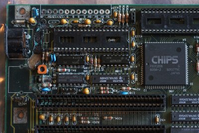
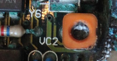
I’d say you have a really good chance at getting that board working well again. It looks like the battery corroded the 12V trace to the point where resistive heating burnt the PCB and may have also set off the orange tantalum capacitor near the AT power connector. The corrosion from the battery does not look too bad compared to boards that have successfully been repaired.

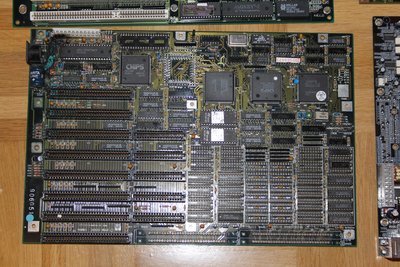
Your board is most likely a 4 layer board as follows:
L1 = signal traces (top)
L2 = ground plane
L3 = +5V plane
L4 = signal traces (bottom)

I think you’re assumptions are right. The fuse connects the internal 5V plane to the keyboard and the only sensible traces on the top layer that are completely missing are the +12 and -12 rails. The unpopulated component L4 and it’s partner should connect to the keyboard plug, just check the continuity there as you may need to rework that trace too.

If you’re really keen on getting this board going, I’d say you could:

1. Clean the affected area with vinegar until you’re certain the potassium hydroxide is neutralized. I do this under hot running water with a soft paintbrush to apply and clean the affected areas. When it looks like its clean, I just fully submerse the board and rinse it a few times for in cold water before quickly drying it with warm air. Don't let the board sit wet for too long as any missed areas will corrode really quickly. Make sure you do this with gloves on and away from anywhere close to food. You should always wear gloves anyway, everything on those corroded boards will leech into your skin.

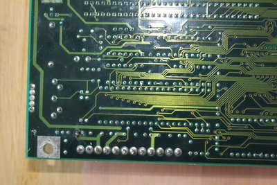
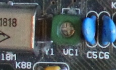
From your cleaned up pictures, you still have a lot of areas that appear to need cleaning that will continue to corrode. It’s up to you to decide if you want to replace the ICs and the RTC trimmer cap but you should really try and halt the corrosion up the 12 rail and inside the ISA slots. It looks like the electrolyte has wicked under the solder mask and will continue to slowly cause issues. Ideally you could remove the ISA slots that cover the really bad areas and re-tin that track.

2. Replace the 12V rails with hookup wire, and using 30 gauge wire-wrap fix any corroded vias. With a lot of flux and a bit of old solder-wick, you can gently remove the damaged mask and re-tin the corroded areas.

3. Replace the CPU socket and missing DRAM. You probably don't need to replace the capacitors for testing.

4. If it’s working, reseal the exposed copper areas with some acrylic conformal coating. It comes in a nail-polish bottle and can be removed if more rework is required.

Always a bit annoying seeing an unused external battery connector 😀 Fingers crossed, looks like a great board.

Reply 5 of 10, by feipoa

User metadata
Rank l33t++
Rank
l33t++

Welcome to the forum!

Does the battery juice makes its way into sealed IC's and solid state components? I've noticed that, even after cleaning, that inductor leads, over the years, will continue to turn blue. So I was wondering if the battery juice at least can makes way into these wirewound through hole inductors? I've decided that I'm going to replace all inductors in the vicinity of battery leaks.

I bring this up because I just noticed that on the DTK board I referenced above, the keyboard inductor lead has turned blue, to the extent that the keyboard doesn't work.

Plan your life wisely, you'll be dead before you know it.

Reply 6 of 10, by Predator99

User metadata
Rank l33t
Rank
l33t

Hi Frog86,

also from my side welcome to the forum and many thanks for your detailed and very useful reply!

I already cleaned the board with vinegar and let it react for about 1h. Afterwards I cleaned with water, then grain alcohol and dried with a hair dryer. The result you can see on the photo. There are still some green areas, but these must be mainly inside and I dont want to do a further damage by removing it. Im organic chemist and used to work with much more dangerous agents 😉

I also dont think that the corrosion will continue when the battery is removed - I think everything already reacted and the corrosion has stopped now?

Yes, I am willing to repair this board. However, I am rather unexperienced with soldering work and I do not have professional equipment. I already failed with the 1st try to install a new socket, but I already ordered a 2nd one and I am sure I will get it the next time...

Its very interesting and I hear the first time that the whole Layer 3 is a single plane. I think that one can see it by holding the board against a bright light..can send a photo later.

Reply 7 of 10, by Predator99

User metadata
Rank l33t
Rank
l33t

Enough for today 😵 Installed a new CPU socket and inserted a CPU.

Soldered the 2 caps and attached wires where I intended to connect the ISA bus to. I was thinking that the board should power on without the 12 V lines connected and I tried it. As expected, the +12V / -12V lights on the card did not light and a number was diaplayed on the card.

I measured the voltage on the 2 wires against ground and there was nothing...

Then...the cap that I used to replace the one that was totally destroyed as I received the board started to burn! 😠

I removed even more from the PCB with a screwdriver and everything was green below that CAP....this area is a total shortage I think...

Reply 8 of 10, by Predator99

User metadata
Rank l33t
Rank
l33t

Does anybody know what components these are and if I can test it? There seems to be a cross in the middle, something adjustable? Its labeled as "VC"?

vc2.jpg
Filename
vc2.jpg
File size
15.99 KiB
Views
524 views
File license
Fair use/fair dealing exception
vc1.jpg
Filename
vc1.jpg
File size
91.01 KiB
Views
525 views
File license
Fair use/fair dealing exception

Reply 9 of 10, by Jo22

User metadata
Rank l33t++
Rank
l33t++

These are either variable resistors or variable capacitors, I guess.
Caps can be used to modify the frequency of xtals a tiny little bit.

"Time, it seems, doesn't flow. For some it's fast, for some it's slow.
In what to one race is no time at all, another race can rise and fall..." - The Minstrel

//My video channel//