VOGONS


First post, by mcobit

User metadata
Rank Member
Rank
Member

Finished

20180605_160659.jpg
Filename
20180605_160659.jpg
File size
912.38 KiB
Views
988 views
File license
Fair use/fair dealing exception

Hello,
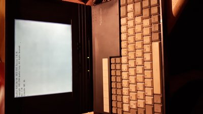
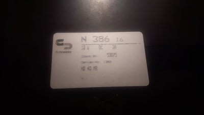
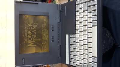
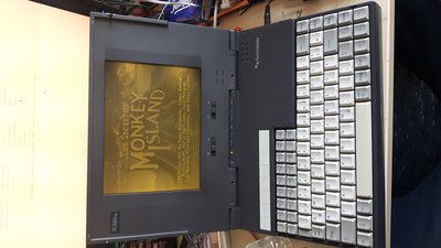
Today I got a Schneider N 386 16 notebook from the flee market for 2 Euros. It is not in the best condition but seems to work fine except for a fixed disk controller error when posting. The HDD makes klicking noises so I guess it's dead.

Now for the tricky part: I have no clue how to open it as the hdd is not accessable from the outside.
There are no visible screws. Not even under the rubber feet at the back. Do I have to unclip it somehow. Don't want to damage the shell if it can be avoided.

Anyone has experience with this type of machine?
Some pictures are in the attachment.
Attachments

  • 20180510_211335.jpg
    Filename
    20180510_211335.jpg
    File size
    877.63 KiB
    Views
    1251 views
    File license
    Fair use/fair dealing exception
  • 20180510_211142.jpg
    Filename
    20180510_211142.jpg
    File size
    639.77 KiB
    Views
    1251 views
    File license
    Fair use/fair dealing exception
Last edited by mcobit on 2018-06-05, 16:22. Edited 2 times in total.

Reply 1 of 17, by mcobit

User metadata
Rank Member
Rank
Member

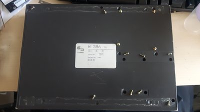
Ok. Now I know where the screws are. Under the plastic stickers on the back.

Now I will turn this into a repair thread and post progress how I get along.

Attached is a photo of the screw positions.

Attachments

  • 20180511_081640.jpg
    Filename
    20180511_081640.jpg
    File size
    707.22 KiB
    Views
    1205 views
    File license
    Fair use/fair dealing exception

Reply 2 of 17, by mcobit

User metadata
Rank Member
Rank
Member

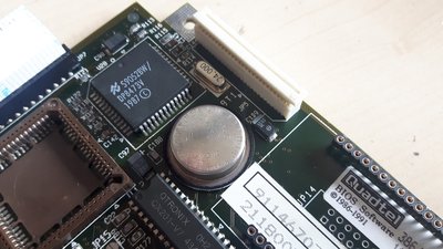
The bios battery is empty but it is some strange 3.6V lithium cell soldered directly to the board. I removed it and the solderpads look like maybe I can replace it with a normal 3V cell holder. 3V should be sufficient for some time. The old cell is at 120mV so absolutely flat.

Edit: I had a look on Ebay and those batteries sell for a furtune and only come from China. So I will definately use some replacement.

Attachments

  • 20180511_122023.jpg
    Filename
    20180511_122023.jpg
    File size
    977.3 KiB
    Views
    1163 views
    File license
    Fair use/fair dealing exception
Last edited by mcobit on 2018-05-13, 09:36. Edited 1 time in total.

Reply 3 of 17, by mcobit

User metadata
Rank Member
Rank
Member

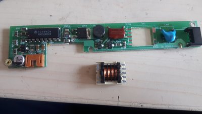
Removed the screen and the transformer fell off the inverterboard directly. Seems like the solder never really flow on the pads correctly. Resoldered it and it seems solid now. This could explain the fluctuation of the backlight when pressing down on the inverter board through the case.

Attachments

  • 20180511_101016.jpg
    Filename
    20180511_101016.jpg
    File size
    804.67 KiB
    Views
    1162 views
    File license
    Fair use/fair dealing exception
Last edited by mcobit on 2018-05-13, 10:30. Edited 1 time in total.

Reply 4 of 17, by mcobit

User metadata
Rank Member
Rank
Member

As the floppy drive made strange noises when a disk is inserted and could not read any disks, I took that apart, too.
Looks like the drivebelt broke in half and so the motor was rotating endlessly without being able to seek.
Ordered some replacement on Amazon, but as it comes from China, it will take a Month or so to arrive...

Attachments

  • IMG_6811.JPG
    Filename
    IMG_6811.JPG
    File size
    1.14 MiB
    Views
    1153 views
    File license
    Fair use/fair dealing exception

Reply 5 of 17, by mcobit

User metadata
Rank Member
Rank
Member

Also removed the HDD. This seems to have a normal 44 pin mini ide connector, so replacement should be easy. Maybe with some SD card adapter. The Bios seems to have a limit of 512MB, so I need to find some small SD card. The HDD just clicks when trying to power up even on an adapter on my pc. Not sure if I will try to open it carefully and try to unblock the readheads. It is one of the 2.5" drives with full height (double the height of todays notebook drives).

Attachments

  • IMG_6810.JPG
    Filename
    IMG_6810.JPG
    File size
    1.02 MiB
    Views
    1153 views
    File license
    Fair use/fair dealing exception
  • IMG_6808.JPG
    Filename
    IMG_6808.JPG
    File size
    1.14 MiB
    Views
    1153 views
    File license
    Fair use/fair dealing exception
Last edited by mcobit on 2018-05-13, 11:13. Edited 1 time in total.

Reply 6 of 17, by Tiido

User metadata
Rank l33t
Rank
l33t

That drive is guaranteed to have bad capacitors on it, the exact same types fail with 100% certainity in Sega Game Gears and other hardware using those.

T-04YBSC, a new YMF71x based sound card & Official VOGONS thread about it
Newly made 4MB 60ns 30pin SIMMs ~
mida sa loed ? nagunii aru ei saa 😜

Reply 7 of 17, by mcobit

User metadata
Rank Member
Rank
Member

Also here are some pictures of the completete motherboard. There even is an empty socket for a co-processor.
Not sure what the dual pinheaders at the lower right are. Maybe for a ram expansion? If anybody has an idea, let me know.
The upper male 44 pin connector is for the HDD. But I have no clue what the blue female one is for.

Attachments

  • IMG_6794.JPG
    Filename
    IMG_6794.JPG
    File size
    1.21 MiB
    Views
    1152 views
    File license
    Fair use/fair dealing exception
  • IMG_6791.JPG
    Filename
    IMG_6791.JPG
    File size
    1.05 MiB
    Views
    1152 views
    File license
    Fair use/fair dealing exception

Reply 8 of 17, by mcobit

User metadata
Rank Member
Rank
Member
Tiido wrote:

That drive is guaranteed to have bad capacitors on it, the exact same types fail with 100% certainity in Sega Game Gears and other hardware using those.

Thanks for your post. In this case it could be that it can't provide the power to move the heads. I will definately try to replace them. Do you know where to source them from?

Reply 9 of 17, by mcobit

User metadata
Rank Member
Rank
Member

Here is the power supply board. Seems to be some old switchmode design. The electrolytic caps seem to be in good condition. May replace them anyway though.
I noticed a lot of bodge wires and added components (diodes, wires, transistors soldered directly to vias) all around this pc. Maybe this is some early model.

Attachments

  • IMG_6800.JPG
    Filename
    IMG_6800.JPG
    File size
    916.68 KiB
    Views
    1148 views
    File license
    Fair use/fair dealing exception
  • IMG_6798.JPG
    Filename
    IMG_6798.JPG
    File size
    755.74 KiB
    Views
    1148 views
    File license
    Fair use/fair dealing exception

Reply 10 of 17, by Tiido

User metadata
Rank l33t
Rank
l33t

Just use anything with same or smaller physical size and capcitance ratings. There are no voltages above 5V there so 6.3V or higher voltage rating capacitors will do. I see two 100µF, two 68µF and one 10µF.

T-04YBSC, a new YMF71x based sound card & Official VOGONS thread about it
Newly made 4MB 60ns 30pin SIMMs ~
mida sa loed ? nagunii aru ei saa 😜

Reply 11 of 17, by mcobit

User metadata
Rank Member
Rank
Member

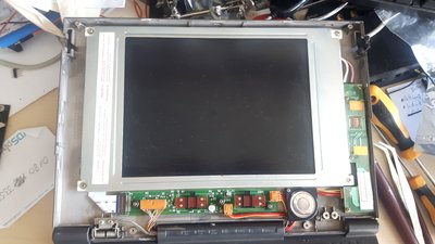
And the last post for today. There is the display assembly. The board unter the lcd has two potentiometers. One for brightness and one for contrast. Both were a little sticky so I cleaned them. The rest seems fine.

Attachments

  • 20180511_100250.jpg
    Filename
    20180511_100250.jpg
    File size
    954.08 KiB
    Views
    1148 views
    File license
    Fair use/fair dealing exception

Reply 12 of 17, by mcobit

User metadata
Rank Member
Rank
Member
Tiido wrote:

Just use anything with same or smaller physical size and capcitance ratings. There are no voltages above 5V there so 6.3V or higher voltage rating capacitors will do. I see two 100µF, two 68µF and one 10µF.

Yeah, some of them look like they became a bit hot as the silkscreen is almost completetly destroyed. Maybe I can get some smaller round electrolytics that will fit. The ones that are on there seem to have the advantage that they don't seem to leak though.
The PSU board also has some of those. Will have to count and replace them all.

Reply 13 of 17, by Tiido

User metadata
Rank l33t
Rank
l33t

They absolutely do leak, I'm pretty sure you'll smell rotting fish when you try to desolder them... There should be 5mm of clearance and it is easy to find suitable capacitors that fit in place.

T-04YBSC, a new YMF71x based sound card & Official VOGONS thread about it
Newly made 4MB 60ns 30pin SIMMs ~
mida sa loed ? nagunii aru ei saa 😜

Reply 14 of 17, by mcobit

User metadata
Rank Member
Rank
Member

Got the new belts for the floppy drive today. It is back in working oder. Also replaced the harddrive with an SD Card adapter. Boots fine now. Still have to get a coincell holder and have to 3D print a new powerswitch as the old one is cracked.
Also replaced two capacitors on the display controller what made the contrast a lot more stable.

Reply 16 of 17, by mcobit

User metadata
Rank Member
Rank
Member

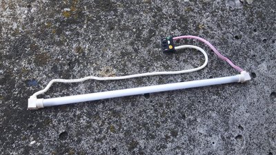
Attached is a photo of the broken tube.
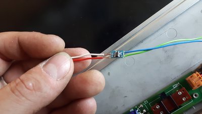
I had some 20mA constant current sources from another project. As there are 19V to drive the display on the display controll board, I just used that to drive two warm white leds placed in the gap where the tube used to sit.
Works great. Although not perfect as you can see on the other picture. There are darker spots as the leds have a more focused beam.
That doesn't bother me too much though as it is a hundered percent better than without backlight.

I like the warm white backlight. Adds some old Monitor touch. Maybe I will try amber leds in the future.

Now let's party like it's 1991!

Attachments

  • 20180605_134126.jpg
    Filename
    20180605_134126.jpg
    File size
    1.97 MiB
    Views
    995 views
    File license
    Fair use/fair dealing exception
  • 20180605_142609.jpg
    Filename
    20180605_142609.jpg
    File size
    843.31 KiB
    Views
    995 views
    File license
    Fair use/fair dealing exception
  • 20180605_151912.jpg
    Filename
    20180605_151912.jpg
    File size
    868.45 KiB
    Views
    995 views
    File license
    Fair use/fair dealing exception

Reply 17 of 17, by mcobit

User metadata
Rank Member
Rank
Member

Revisited the backlight part again. I wanted a better light distribution. So I cut an led strip from a salvaged led monitor to size and found that I can drive 3 of the leds (one led of those has 2 chips in series) in series with a 1k resistor to get sufficient brightness.
So I used a strip of 9 leds and modified it so that always 3 are in series. The original used a 40V supply to drive 8 in series.

Then soldered everything together. This should give a good lifetime as the leds are only driven by 1/4th of their rated current. The whole circuit draws 20mA what should also be a lot more efficient than the old tube at a similar brightness.