I am confused by the question. The layout for the Chaintech 486SPM is different than the MSI MS-4144. I didn't do a write-up for the MS-4144.
Where is r147? Do you have a photo? Which board are you referring to? If you have a photo explaining what you are looking for, I can dig out my MS-4144 board. Didn't another user mod his MS-4144 board that you can contact as well?
Plan your life wisely, you'll be dead before you know it.
yes - both boards have a different layout., but your worksheet refers to the MS-4144 (top left corner) or did I misunderstand that?.
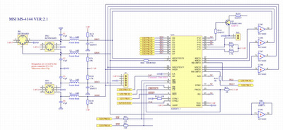
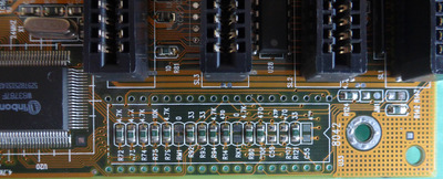
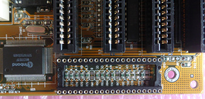
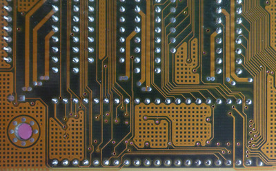
The photo shows the position of R147 on MS-4144 Ver. 2.1.
Unfortunately after intensive research I have not found anyone who has already modified this.
Oh, I don't even remember submitting my pencil-to-paper worksheet on the MS-4144 ps/2 mouse mod. R147 is a convenient location to connect IRQ12 to the KBC pin 36. You will want to short the R147 pads together with a wire, or use a 0-ohm resistor. I wanted to be more involved on my board, so I soldered in a jumper header at R147. Aside from the R147 short, it looks like you just need two capacitors, and two inductors. I don't recall if any modifications are needed under the KBC socket. I don't think so, but would have to see a photo of your board with the KBC removed to determine that.
Plan your life wisely, you'll be dead before you know it.
I measured the connections (MS-4144_PS_2.txt).
As suggested I will use R147 as solder jumper.
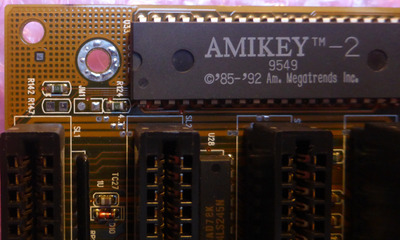
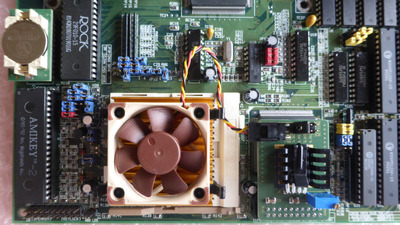
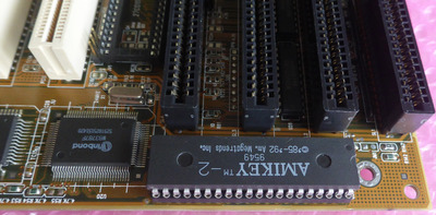
If it doesn't work then I will unsolder the AMIKEY-2 and post a photo.
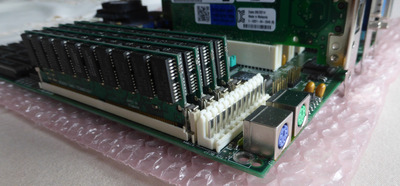
I have some small 19" (2U) cases that I use for this and other projects. These boards are also modified:
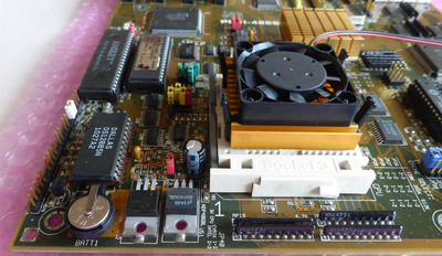
- ASUS PCI/I-486SP3G with PS/2 and modified RTC (DS12887A replacement)
R147 is now a 0R resistor, not jumper. Unfortunately the mouse didn't work - no clock and data on KBC. Looks like mouse disabled, but mouse is enabled in BIOS. Tried other KBC, the same result. Any suggestions are welcome...
The next bad news: The board will not boot with the AWARD BIOS (any version). The only change was to upgrade the L2 cache to 1024 KB. No problems with the AMI BIOS.
Niemand ist nutzlos, er kann immer noch als schlechtes Beispiel dienen...
I checked under my KBC, and our PCB's are the same in terms of which components are soldered and not soldered on.
You tried AWARD BIOS Version WF54S?
You say the board "will not boot". What does that mean exactly? The screen stays blank when you power up, or the system hangs at or before POST?
Not sure what to advise. Put 256K back in for starters. Map out all traces to ensure they are connected properly. I've noticed that some boards need some pins lifted up on the KBC if the board isn't wired for PS/2 mice, but my MS-4144 didn't need this. Follow this diagram: Re: DTK PKM-0033S +5V pin overheating + PS/2 mouse implementation Not that the KBC pins are not in order on this HOLTEK diagram, which is particularly irritating.
Plan your life wisely, you'll be dead before you know it.
Not sure what to advise. Put 256K back in for starters. Map out all traces to ensure they are connected properly. I've noticed that some boards need some pins lifted up on the KBC if the board isn't wired for PS/2 mice, but my MS-4144 didn't need this. Follow this diagram: Re: DTK PKM-0033S +5V pin overheating + PS/2 mouse implementation Not that the KBC pins are not in order on this HOLTEK diagram, which is particularly irritating.
Downgrade to 256KB the result is same. The board will start only with AMI...
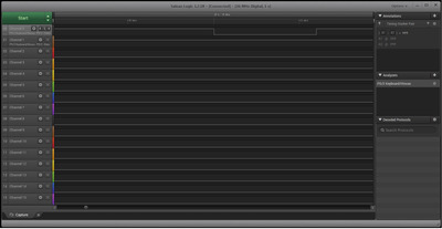
No mouse timing still on the KBC, but when I press a button, a low pulse is generated on the PIN39. I think the KBC was not initialized correctly.
Extract from the VT82C42 data sheet:
TEST0(1) is expected to connect to KBCLK no matter what mode the VT82C42 is in. TEST1(39) is expected to connect to KBDATA when in AT-mode, and is expected to connect to MSCLK when in PS/2 mode.
There is no jumper header at JM1, just solder pads. The solder pads are open (not shorted).
I suggest following that Holtek diagram to ensure your KBC is wired properly. It is possible that your board wasn't wired for the PS/2 mouse, while my revision was. If your board was not wired for the PS/2 mouse, you may need to do some hacking like I did on my DTK PKM-0033
Plan your life wisely, you'll be dead before you know it.
My board has REV. 2.1, later revisions are not known to me. I think this was the last revision and AMI has PS/2 mouse support in the latest AF54S BIOS.
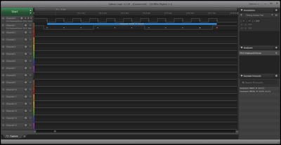
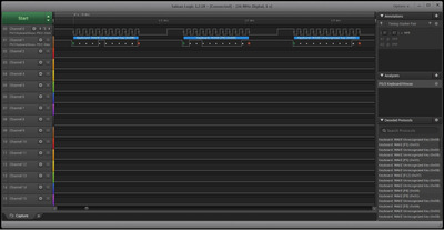
Here a mouse timing taken from ASUS PCI/I-486SP3G. Pin39 is clock and PIN28 is data. PIN21(RC) and PIN22(A20) is here wired. I'll check that later...
@feipoa:
Good news - PS/2 mice works with your modified AWARD BIOS! I have testet AMIKEY-2 and VT82C42N. The AMI BIOS AF54S seems to have a bug... The last schematic update above in my thread.
Now I'm done and glad...
Niemand ist nutzlos, er kann immer noch als schlechtes Beispiel dienen...