VOGONS


First post, by kdr

User metadata
Rank Member
Rank
Member

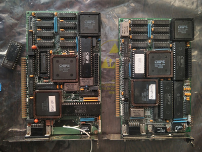
I've been investigating a pair of ancient Sigma Designs EGA cards that I got a while back from a pile of untested ISA boards.

IIMG_20201009_152955.jpg
Filename
IIMG_20201009_152955.jpg
File size
677.48 KiB
Views
1706 views
File comment
SPEGASYNC and ERGO480
File license
CC-BY-4.0

One of the cards (the SPEGASYNC) works nicely in my Turbo XT at 4.77Mhz, but utterly fails in turbo mode at 10Mhz. Both the RAM (120ns) and ROM (?) appear to be too slow. The other card (the ERGO480) fails to POST and even manages to lock the system up. But I have high hopes for it, because the RAM is faster (100ns). Thus begins the investigation...

The BIOS strings claim these are UNISYS cards. (Didn't know UNISYS made ISA graphics cards!)

The SPEGASYNC is a pretty standard early EGA card from 1986. 256KB of RAM and using the CS8240 chipset from CHIPS. Plus a Sigma Designs gate array, the L1A2334, to hold all the 'glue' logic to connect the EGA chips to the ISA bus. BIOS string says "UNISYS ENHANCED GRAPHICS CONTROLLER VERSION 1.30". It works nicely at 4.77Mhz and does all the typical EGA stuff.

On the subject of "does every EGA card have 256KB?" -- the August 1986 issue of PC Magazine, immediately after the first EGA clones came on the market, reviews 12 different EGA cards (IBM's plus 11 clones). All of the cards offer a 256KB memory option, but even more interesting is that only three of the cards (the IBM plus two clones) are available in a 64KB configuration.

But I want an EGA card that works in my Turbo XT at 10Mhz! So let's try the ERGO480.... it has two oscillators onboard, a 28.500Mhz and a 32.000Mhz; hmm, very close to 2x of the standard 14.318Mhz OSC signal and the 16.257Mhz oscillator that one expects an EGA card to use. No matter what I do, can't find the right switch settings to get this thing to POST and output a proper 15.7khz or 21.8khz sync. As a bonus, it usually also freezes the system, preventing it from even booting!

Progress is made once I pull the ROM off the card. This reveals a curious PAL16L8 hidden underneath the ROM socket, which is a bank switcher -- do an I/O write to port 03CBh and bit D0 switches between the two 16KB banks. The card maps the ROM at C000-C3FF. (Why Sigma bothered with this bank switching scheme instead of just mapping the whole 32KB to C000-C7FF is a real mystery.) I stuck the ROM into an Ethernet card's boot ROM socket and dumped the whole 32KB.

With the ERGO480 card now ROMless, I can install it alongside an MDA card and my machine is able to boot.

I can poke the standard EGA registers and bring the card up. Programming the sequencer and CRTC according to the values from IBM's EGA Technical Reference is enough to get an 80x25 text mode display up and running -- at 31.5khz hsync! Hmmm, better not plug in the CRT just yet. [If only I had an early NEC Multisync with TTL digital inputs.] The video RAM at B800 is accessible and works fine, even in 10Mhz turbo mode. I change the I/O base address jumper on the card (moving it from the standard 3C0-3CF ports to the alternate 2C0-2CF ports) so that I can both with the video BIOS ROM installed, because the ROM doesn't support (and can't detect) the card if it's at the alternate address. And I was able to confirm that the ROM is also fast enough to work reliably in turbo mode at 10Mhz.

Yes, this means it is possible to have *three* video cards installed in an XT! One MDA or CGA adapter, plus one EGA adapter at the standard 03Cx and 03Bx/03Dx ports, plus a *second* EGA adapter at the alternate 02Cx/02Bx/02Dx ports. But there's zero BIOS or DOS support for that EGA at the alternate address. Did any software or operating system ever take advantage of this ability?

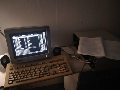
Now it's time to debug the video BIOS! I tried just jumping to the initialization code at C000:0003, but it kept getting confused into thinking it was in monochrome mode and started reprogramming the CRTC in my MDA adapter, whoops! So instead I rigged up a way to load the video BIOS dump into RAM and execute it from there. Required patching up the bank-switching trampolines to modify the CS register instead, and also had to patch up a couple of hard-coded references to the C000 segment, but... it worked! I was able to single-step through the BIOS in Turbo Debugger, skipping over any questionable bits as needed. As a bonus, TD seems to have its own MDA support that doesn't rely on any BIOS routines, and is very aggressive about reprogramming the MDA to known-good values every time it hits a breakpoint.

IMG_20201008_195940.jpg
Filename
IMG_20201008_195940.jpg
File size
157.25 KiB
Views
1706 views
File comment
Video BIOS debugging session
File license
CC-BY-4.0

Finally I can figure out why this card goes off the rails! And also maybe figure out what the switch settings are!

As it turns out, a couple of the DIP switches were faulty. No wonder I couldn't figure out the settings. Liberal application of IPA resolved the issue. Many of the switch settings are "standard", same as on the IBM EGA. Once I found a setting that worked (SW1..4=OFF:ON:ON:ON for colour 80-columns on a 200-line monitor) the BIOS was able to POST and write its version string to the primary display (the MDA). But then it failed its self-test, beeped out the familiar long-short-short-short code, and promptly froze the system.

By single-stepping my way through the self-test, the issue was easily identified: a bad DRAM chip on bits D0-D3 of plane #3. The memory test activates the A000 mapping for the video RAM and then tests each plane, one by one. When the test fails, it beeps out the code but then continues executing the rest of the video BIOS initialization instead of bailing out.

So it bravely carries on to the next step, which is calling its own INT 10h handler with AX=CE01h, which is some sort of proprietary Sigma extension to the standard INT 10h interface. Most likely to handle the CGA emulation. And that's what is in the second bank of the ROM: a copy of the SIGMAEGA.COM emulation utility! It even has a bunch of help text describing the various commandline options available. How weird. Anyway, the AH=CEh handler has to set up some kind of 'sane' environment before it can execute the emulation code, and it does so in the A000 segment -- which was oh-so-conveniently left enabled by the RAM self-test code.

Too bad that plane #3, which is the one left enabled, is the one with bad RAM in it. Chaos ensues and things quickly go off the rails, and the system appears to freeze because the CPU is off in never-never-land executing total garbage.

Guess it's time to order some new RAM.....

Anyway, this L1A2334 chip appears to contain a bunch of CGA emulation hardware in addition to the expected bus interface glue logic. What I've found so far:

03CB: write-only register for ROM bank switching
bit D0 controls the bank, 0=low 16KB, 1=high 16KB
03CD: read/write register holding emulation mode status (?)
bit D0 seems to be some kind of reset - clear this bit and the EGA I/O ports 'disappear'
bits D3 and D7 appear to control the emulation mode
03x9: read/write register (this is the CGA and Hercules mode control register)
not clear if anything happens on writes to this register, or if it's there to remember whatever value the CGA program has written

The data bus from the ISA slot is routed (via an LS245) to the card's internal data bus. The L1A2334 sits on this bus, along with the ROM, the PAL16L8 bank switcher, a PAL16L8 that acts as a CLKSEL multiplexer, and the 82C43x chips. What's weird is that D3 and D7 from the ISA slot only go to the L1A2334, and D3 and D7 on the card's internal data bus are only connected to the L1A2334. So it has some sort of ability to intercept or modify these bits as they move between the ISA slot and the 82C43x chips. Very interesting.
Reply 1 of 32, by Predator99

User metadata
Rank l33t
Rank
l33t

Many thanks for uploading the BIOS images first!

Thats really cool what you have done there and I also enjoy doing things like that, Turbo Debugger is also my favorite tool 😀
I also planned to try to boot a PC with MGA as primary video and a EGA/VGA without BIOS as secondary and try to initialize it with a TSR based on a BIOS dump. You have shown that its works. Very nice!

Its new to me that its possible to select the base adress of a EGA card. If you like to use 2 cards at once you also have to select another RAM segment for the 2nd one?

Dont understand however what the PAL and LS chips do..still learning 😉

Reply 2 of 32, by kdr

User metadata
Rank Member
Rank
Member
Predator99 wrote on 2020-10-09, 14:17:

Its new to me that its possible to select the base adress of a EGA card. If you like to use 2 cards at once you also have to select another RAM segment for the 2nd one?

Well, first problem is that both EGA cards' address decoders will select their ROM for the C000 segment - I think this means you need the exact same ROM on both cards, otherwise they'll both try to drive the bus with different data bits.... it's not entirely clear to me how dual EGA was even meant to work. [And why did IBM even put that jumper on the card if the BIOS didn't support the alternate base address?]

As for the RAM segments, I can think of a couple ways to manage... GR06 register can set the memory segment to A000-AFFF, B000-B7FF, or B800-BFFF. So you could set each EGA card to a different segment. Another option would be to use bit D1 of port 3C2/2C2 (the miscellaneous output register) to enable/disable the RAM... so both cards could have the full 64K mapped at A000, and just take turns accessing them. [The card will continue to output video, the enable RAM bit only affects the CPU accesses.]

I wonder if any software ever tried to do this? Maybe some high-end CAD tools?

Reply 3 of 32, by the3dfxdude

User metadata
Rank Member
Rank
Member
kdr wrote on 2020-10-09, 03:32:
But I want an EGA card that works in my Turbo XT at 10Mhz! So let's try the ERGO480.... it has two oscillators onboard, a 28.5 […]
Show full quote

But I want an EGA card that works in my Turbo XT at 10Mhz! So let's try the ERGO480.... it has two oscillators onboard, a 28.500Mhz and a 32.000Mhz; hmm, very close to 2x of the standard 14.318Mhz OSC signal and the 16.257Mhz oscillator that one expects an EGA card to use. No matter what I do, can't find the right switch settings to get this thing to POST and output a proper 15.7khz or 21.8khz sync. As a bonus, it usually also freezes the system, preventing it from even booting!

...

I can poke the standard EGA registers and bring the card up. Programming the sequencer and CRTC according to the values from IBM's EGA Technical Reference is enough to get an 80x25 text mode display up and running -- at 31.5khz hsync! Hmmm, better not plug in the CRT just yet. [If only I had an early NEC Multisync with TTL digital inputs.] The video RAM at B800 is accessible and works fine, even in 10Mhz turbo mode. I change the I/O base address jumper on the card (moving it from the standard 3C0-3CF ports to the alternate 2C0-2CF ports) so that I can both with the video BIOS ROM installed, because the ROM doesn't support (and can't detect) the card if it's at the alternate address. And I was able to confirm that the ROM is also fast enough to work reliably in turbo mode at 10Mhz.

...

...

As it turns out, a couple of the DIP switches were faulty. No wonder I couldn't figure out the settings. Liberal application of IPA resolved the issue. Many of the switch settings are "standard", same as on the IBM EGA. Once I found a setting that worked (SW1..4=OFF:ON:ON:ON for colour 80-columns on a 200-line monitor) the BIOS was able to POST and write its version string to the primary display (the MDA). But then it failed its self-test, beeped out the familiar long-short-short-short code, and promptly froze the system.

You should consider yourself lucky. I also been down a similar path the past few weeks and a few different EGA cards, the worst one being an IBM EGA not outputting the correct sync. Ultimately you had a switch problem and I believe my issue is an IC.

Just a few things to mention, since I did similar debugging. On the IBM card's BIOS, it senses the switches and stores the setting in RAM, per the docs. This is the first place I went when I couldn't get the thing to come up as expected on any switch setting. I also probed the switches directly for off and on and it was all fine. I'm not sure if your card stores it in RAM, but it would have been a good thing to check.

I also went down the route of adding a Hercules card as MDA to get a screen up, dump the ROM, check the RAM, etc. When the ROM checked out and the RAM did not, I decided to go maybe a safer(?) route of pulling the Hercules card, the EGA ROM, and running a serial terminal to the PC. Then I poked all the EGA registers in debug.com for 3 different modes. Unfortunately doing a schematic analysis and checking the different frequencies coming out of the sequencer pretty much told me it wasn't taking the commands. Anyway I had to give up on that at that point in interest of time.

Going back to when you mentioned there are two oscillators on board. I would be surprised that the card does not use the ISA bus's 14Mhz clock and instead clock divides the 28Mhz. I'm pretty sure my understanding on working on another one of these "480" EGA cards is that 16Mhz is for hi res EGA, and 28Mhz is for Super-EGA. Which brings me to a pain point, because this actually breaks compatibility with IBM's original design, at least on my Genoa card. I couldn't do what I needed on the feature connector, and had to get an actual IBM card.

I think some late EGA cards might have gone to putting the low res mode clock on board (some have 3 oscillators) in case of faster bus. If that is how it works with the 28Mhz, then I guess it could clock divide!

Yes, this means it is possible to have *three* video cards installed in an XT! One MDA or CGA adapter, plus one EGA adapter at the standard 03Cx and 03Bx/03Dx ports, plus a *second* EGA adapter at the alternate 02Cx/02Bx/02Dx ports. But there's zero BIOS or DOS support for that EGA at the alternate address. Did any software or operating system ever take advantage of this ability?

I'm thinking that the alternate port address was to do basically you did; test the card without conflicting with another. (CGA?) So I think it was for late stage testing of the EGA design, but since CGA compatibility was a feature, the card shipped at 3xx in the BIOS to the consumer, so no new software was needed.

Reply 4 of 32, by mkarcher

User metadata
Rank l33t
Rank
l33t
kdr wrote on 2020-10-09, 03:32:

Too bad that plane #3, which is the one left enabled, is the one with bad RAM in it. Chaos ensues and things quickly go off the rails, and the system appears to freeze because the CPU is off in never-never-land executing total garbage.

Guess it's time to order some new RAM.....

When you run the BIOS code in turbo debugger, you might want to just patch the segment for the emulation data from A000 to something inside conventional memory to not depend on the broken RAM in bank 3. You can continue exploring that card in more detail until you get to install the replacement RAM that way.

Reply 5 of 32, by kdr

User metadata
Rank Member
Rank
Member
the3dfxdude wrote on 2020-10-09, 21:53:

Just a few things to mention, since I did similar debugging. On the IBM card's BIOS, it senses the switches and stores the setting in RAM, per the docs. This is the first place I went when I couldn't get the thing to come up as expected on any switch setting. I also probed the switches directly for off and on and it was all fine. I'm not sure if your card stores it in RAM, but it would have been a good thing to check.

I also went down the route of adding a Hercules card as MDA to get a screen up, dump the ROM, check the RAM, etc. When the ROM checked out and the RAM did not, I decided to go maybe a safer(?) route of pulling the Hercules card, the EGA ROM, and running a serial terminal to the PC. Then I poked all the EGA registers in debug.com for 3 different modes. Unfortunately doing a schematic analysis and checking the different frequencies coming out of the sequencer pretty much told me it wasn't taking the commands. Anyway I had to give up on that at that point in interest of time.

Yeah, I've learned a lot about how the EGA BIOS works thanks to all of this, and also found that (unsurprisingly) the Sigma BIOS uses the same memory locations in the BIOS data area (0400h) as the IBM EGA BIOS. Including storing the switch settings etc. So next time I have to debug one of these EGA cards, I'll be able to make progress much faster!

the3dfxdude wrote on 2020-10-09, 21:53:

Going back to when you mentioned there are two oscillators on board. I would be surprised that the card does not use the ISA bus's 14Mhz clock and instead clock divides the 28Mhz. I'm pretty sure my understanding on working on another one of these "480" EGA cards is that 16Mhz is for hi res EGA, and 28Mhz is for Super-EGA. Which brings me to a pain point, because this actually breaks compatibility with IBM's original design, at least on my Genoa card. I couldn't do what I needed on the feature connector, and had to get an actual IBM card.

I think some late EGA cards might have gone to putting the low res mode clock on board (some have 3 oscillators) in case of faster bus. If that is how it works with the 28Mhz, then I guess it could clock divide!

That's what I would have assumed, but I confirmed that there's NO WAY to send OSC to the 82C432 sequencer! The video BIOS programs the CRTC with the appropriate values to generate 15.7khz hsync (identical to the values used on the IBM EGA) but that obviously doesn't work, right? Well, the 82C434A CRTC has an extra register at F9h called the "400 Line Register" which controls an *additional* divide-by-2 stage that sits between CLKIN and the rest of the CRTC. The video BIOS programs this register and et viola! Out comes the expected ~15.7khz hsync, even though the sequencer's CLKIN pin is being fed 28.500Mhz. It's actually 15.625khz but that's close enough.

So that renders this card useless for what I'm intending to do: 8088MPH-style register manipulations during the active video period. Which relies on having the 8254 PIT timer and the EGA CRTC both running from the same clock. (Obviously only in the 200 line modes.) Even though EGA offers a vertical interrupt on IRQ2, it only gets triggered once the vertical blanking period has already begun, meaning I can't really use it.

Luckily there is a spot on the board marked 'SPARE OSC' that goes to a spare clock input on the PAL16L8 that selects which clock is fed to the sequencer's CLKIN. So while I'm replacing the bad RAM chip I can also jumper that input to the ISA slot OSC. Although I'm tempted to replace the 32.0 oscillator with a 16.257 and remove the 28.5 entirely.... so that the board will be 100% EGA compatible.

VOGONS readers, would it be a great sin to permanently alter what could be the only living example of an ERGO480 card? 😀

Reply 6 of 32, by kdr

User metadata
Rank Member
Rank
Member
mkarcher wrote on 2020-10-09, 22:49:

When you run the BIOS code in turbo debugger, you might want to just patch the segment for the emulation data from A000 to something inside conventional memory to not depend on the broken RAM in bank 3. You can continue exploring that card in more detail until you get to install the replacement RAM that way.

Yep, in the end I just stubbed the INT 10h handler to ignore any calls with AH=CEh, because I'm not ready to dive deeper into the CGA emulation yet.

Now that I've seen the Sigma BIOS in detail, I've come to the conclusion that the CHIPS implementation of EGA is pretty much a 100% perfect clone of IBM's design. Since the SPEGASYNC card already has the correct clock configuration (ISA OSC and 16.257Mhz), perhaps I should try booting the card using the IBM EGA BIOS. I suspect it'll work flawlessly.

Reply 7 of 32, by mkarcher

User metadata
Rank l33t
Rank
l33t
kdr wrote on 2020-10-09, 22:57:

VOGONS readers, would it be a great sin to permanently alter what could be the only living example of an ERGO480 card? 😀

Why "permanently"? Socket the clock selection PAL (I suppose it's not the PAL below the ROM), and keep the current PAL and ROM in your parts drawer. You can always go back to the original clock selection PAL and ERGO480 ROM by just swapping two parts. Leave the 28MHz crystal in. You can get 32.514MHz oscillators, so you can replace the 32.000 by 32.514. This will enable you to get perfect EGA clocks, and close enough ERGO480 timings with the original PAL and ROM.

Reply 8 of 32, by kdr

User metadata
Rank Member
Rank
Member

I'd rather leave the PAL well enough alone and just socket the oscillators. Let's see how the RAM replacement goes first.

In the meantime I have the SPEGASYNC installed in my other XT that's running an 8Mhz V20, and that card doesn't appear to require any surgery at all, so the low level EGA fun can continue uninterrupted.

Reply 9 of 32, by the3dfxdude

User metadata
Rank Member
Rank
Member
kdr wrote on 2020-10-09, 22:57:

So that renders this card useless for what I'm intending to do: 8088MPH-style register manipulations during the active video period. Which relies on having the 8254 PIT timer and the EGA CRTC both running from the same clock. (Obviously only in the 200 line modes.) Even though EGA offers a vertical interrupt on IRQ2, it only gets triggered once the vertical blanking period has already begun, meaning I can't really use it.

Luckily there is a spot on the board marked 'SPARE OSC' that goes to a spare clock input on the PAL16L8 that selects which clock is fed to the sequencer's CLKIN. So while I'm replacing the bad RAM chip I can also jumper that input to the ISA slot OSC. Although I'm tempted to replace the 32.0 oscillator with a 16.257 and remove the 28.5 entirely.... so that the board will be 100% EGA compatible.

VOGONS readers, would it be a great sin to permanently alter what could be the only living example of an ERGO480 card? 😀

oooh. So you are basically at the same point I was a couple months back. When I found the Genoa card I had would not work for me due to how it changed the clock selection from IBM's design, I considered whether I needed to pull out the conflicting oscillator to move forward or get another EGA card. Most EGA cards out there had this thing going on, I pretty much didn't want to chance anything (and seeing your card, even though it seems to more closely match the 5 IC configuration of IBM, now seems more justified). I think there are few direct clones, and your reference to Aug 86 PCMag seems to confirm that, so I decided to get an IBM card, since my time is limited.

I didn't research it, but I figured if I changed the card to make it work my way, I needed to learn how the Genoa ROM programs the video controller to be really sure that would be ok. I also felt I'd end up reprogramming the ROM. So of course, same dilemma of modifying what was otherwise a good card. In retrospect, I did study a ROM anyway since I obtained a bad card. Anyhow I'd double check what the Sigma card is actually doing.

Going to your spare osc idea. I saw that on some cards. There are only so many select bits, unless they added another register. If they used the onboard oscillator and clock divided coming out of the sequencer into the ctrc, then I guess they do have a spare ? If it is register compatible, how to activate it? There is also the NC option, which I think is usually the Super-EGA, and the external oscillator, which the latter, is not nice to mess with IMO. I have doubts many of these cards work as intended for the feature connector.

Also, if you have to hack a card, to make your own EGA demo work, it'll be hard to share that with others. So I hope there is an easier way.

Reply 10 of 32, by kdr

User metadata
Rank Member
Rank
Member
the3dfxdude wrote on 2020-10-10, 00:16:

Going to your spare osc idea. I saw that on some cards. There are only so many select bits, unless they added another register. If they used the onboard oscillator and clock divided coming out of the sequencer into the ctrc, then I guess they do have a spare ? If it is register compatible, how to activate it? There is also the NC option, which I think is usually the Super-EGA, and the external oscillator, which the latter, is not nice to mess with IMO. I have doubts many of these cards work as intended for the feature connector.

CLKSEL is bits D2-D3 of the 03C2 register, with four choices according to the IBM EGA Tech Ref: 00=14Mhz, 01=16Mhz, 10=EXT OSC (feature connector), and 11=unused.

I think the usual configuration for "superEGA" cards is to connect the faster oscillators to CLKSEL=10 (since apparently nobody ever used the feature connector EXT OSC support) and CLKSEL=11, while leaving CLKSEL=00 connected to ISA slot OSC and CLKSEL=01 connected to a 16.257Mhz oscillator. This means that the card remains compatible at the register level.

What's been done on the ERGO480 is different: they've connected 28.5Mhz to CLKSEL=00 and 32.5Mhz to CLKSEL=01. CLKSEL=10 still selects EXT OSC from the feature connector, and CLKSEL=11 selects the 'SPARE OSC' pad. Given this selection of oscillators, the only way to achieve "standard" EGA clocks is to use the 82C434A's non-standard "400 line mode" register. So this card has no hope of being register level compatible with a standard EGA unless some hardware modifications are made. I suppose that this card must've been used in some kind of specialized UNISYS environment where 100% EGA compatibility (i.e. works with games that set weird video modes) wasn't needed. As long as you stick to setting modes via the INT 10h video BIOS, it seems like it should work okay.

If you *do* run something that fiddles the registers directly to set a weird video mode, this card will happily send the CRT a nasty 31.5khz or 43khz hsync. Yikes.

the3dfxdude wrote on 2020-10-10, 00:16:

Also, if you have to hack a card, to make your own EGA demo work, it'll be hard to share that with others. So I hope there is an easier way.

The only card hacking that I might do is transforming the ERGO480 back into a 100% compatible EGA clone (because right now it's just a BIOS-compatible clone) which just so happens to be fast enough to work in my 10Mhz Turbo XT... since I probably don't have any hope of ever finding a multisync TTL monitor that can sync at 31.5khz and beyond, this card is otherwise quite useless....

Reply 11 of 32, by mkarcher

User metadata
Rank l33t
Rank
l33t
kdr wrote on 2020-10-10, 00:35:

I think the usual configuration for "superEGA" cards is to connect the faster oscillators to CLKSEL=10 (since apparently nobody ever used the feature connector EXT OSC support) and CLKSEL=11, while leaving CLKSEL=00 connected to ISA slot OSC and CLKSEL=01 connected to a 16.257Mhz oscillator. This means that the card remains compatible at the register level.

What's been done on the ERGO480 is different: they've connected 28.5Mhz to CLKSEL=00 and 32.5Mhz to CLKSEL=01. CLKSEL=10 still selects EXT OSC from the feature connector, and CLKSEL=11 selects the 'SPARE OSC' pad. Given this selection of oscillators, the only way to achieve "standard" EGA clocks is to use the 82C434A's non-standard "400 line mode" register. So this card has no hope of being register level compatible with a standard EGA unless some hardware modifications are made. I suppose that this card must've been used in some kind of specialized UNISYS environment where 100% EGA compatibility (i.e. works with games that set weird video modes) wasn't needed. As long as you stick to setting modes via the INT 10h video BIOS, it seems like it should work okay.

If you *do* run something that fiddles the registers directly to set a weird video mode, this card will happily send the CRT a nasty 31.5khz or 43khz hsync. Yikes.

Wait a second. If the POST sets up some extended configuration register (as I read the datasheet, you can not divide the horizontal clock by two using the 400-line register, so it must be something else) to divide the dot clock by two, all software that just uses regular EGA registers will run at 14.25MHz for CLKSEL=00 and 16.250MHz for CLKSEL=01. This should be close enough to original EGA timing for all monitors to be able to sync that stuff.

While I don't know how the card divides the clock by two, I am positive it's not due to a divide-by-2 feature in the standard EGA registers that would be disabled by software setting custom video modes. If they would use the standard EGA divide-by-2 feature to get from 28.5MHz to 14.25MHz, how would they get to the 7.1256MHz they need for the 40-column text mode and the 320x200 graphics modes?

Reply 12 of 32, by kdr

User metadata
Rank Member
Rank
Member
mkarcher wrote on 2020-10-10, 00:48:

Wait a second. If the POST sets up some extended configuration register (as I read the datasheet, you can not divide the horizontal clock by two using the 400-line register, so it must be something else) to divide the dot clock by two, all software that just uses regular EGA registers will run at 14.25MHz for CLKSEL=00 and 16.250MHz for CLKSEL=01. This should be close enough to original EGA timing for all monitors to be able to sync that stuff.

Actually, that's a good point. So long as the program doesn't do something that causes the CRTC to be reset and lose its register settings, it's unlikely that the program would ever disturb the "400 line mode" register, since it's at index 0F9h. Surely a game wouldn't reset the EGA as part of its modesetting code? I haven't been brave enough to try yet. 😀

mkarcher wrote on 2020-10-10, 00:48:

While I don't know how the card divides the clock by two, I am positive it's not due to a divide-by-2 feature in the standard EGA registers that would be disabled by software setting custom video modes. If they would use the standard EGA divide-by-2 feature to get from 28.5MHz to 14.25MHz, how would they get to the 7.1256MHz they need for the 40-column text mode and the 320x200 graphics modes?

It's an *additional* divide-by-2 stage that comes before the standard divide-by-2 feature that's toggled through CR17.

But now that I read the CS8240 datasheet again (for the millionth time) it sure does seem to imply that CRF9 (400 line register) can't be used as a global CLKIN/2 divider. So now I need to go back and confirm whether or not the ERGO480 BIOS uses the divide-by-2 bit in CR17 to generate its 80-column mode; because if it did, then yes, how would it handle 40-column mode? I can confirm from my notes that the BIOS *does* program CRF9=03 when setting 80x25 CGA textmode, and that what comes out the video connector is indeed a 15.7khz hsync.

Reply 13 of 32, by the3dfxdude

User metadata
Rank Member
Rank
Member
kdr wrote on 2020-10-10, 00:35:

CLKSEL is bits D2-D3 of the 03C2 register, with four choices according to the IBM EGA Tech Ref: 00=14Mhz, 01=16Mhz, 10=EXT OSC (feature connector), and 11=unused.

I think the usual configuration for "superEGA" cards is to connect the faster oscillators to CLKSEL=10 (since apparently nobody ever used the feature connector EXT OSC support) and CLKSEL=11, while leaving CLKSEL=00 connected to ISA slot OSC and CLKSEL=01 connected to a 16.257Mhz oscillator. This means that the card remains compatible at the register level.

Oh, you are right. But that was the conflict on my Genoa card. There are things out there that does use EXT OSC support, hence my issue. That is what most people out there don't know, is it is/was used by IBM, and Super EGA does break that.

But what they did with the modes is definitely not normal as you said. It does otherwise look like you could plop a different ROM on that fixes what is probably otherwise a workable EGA design. So worth a try, doing what you suggest.

Reply 14 of 32, by the3dfxdude

User metadata
Rank Member
Rank
Member
mkarcher wrote on 2020-10-10, 00:48:

While I don't know how the card divides the clock by two, I am positive it's not due to a divide-by-2 feature in the standard EGA registers that would be disabled by software setting custom video modes. If they would use the standard EGA divide-by-2 feature to get from 28.5MHz to 14.25MHz, how would they get to the 7.1256MHz they need for the 40-column text mode and the 320x200 graphics modes?

In the IBM design, there is another register 3c5 called clocking mode register. There is a bit controlling the dot clock. So it's generated in the sequencer in the IBM design, and they should support this, if they were trying to be compatible.

Reply 15 of 32, by rmay635703

User metadata
Rank Oldbie
Rank
Oldbie
kdr wrote on 2020-10-10, 00:35:

If you *do* run something that fiddles the registers directly to set a weird video mode, this card will happily send the CRT a nasty 31.5khz or 43khz hsync. Yikes.

since I probably don't have any hope of ever finding a multisync TTL monitor that can sync at 31.5khz and beyond, this card is otherwise quite useless....

If your not afraid of turning dials inside your fixed frequency TTL monitors just do what I did with my 1988 Compaq mono VGA screen.

When I was poor and young and wanted SVGA , I found that it could be tuned for 1024x768x60hz,
but if I wanted VGA I had to turn things back.

Some rather ancient screens have a LOT of trim, if they have enough you could tune one up for your ega card instead of tuning your EGA card.

Reply 16 of 32, by kdr

User metadata
Rank Member
Rank
Member
the3dfxdude wrote on 2020-10-10, 01:28:

In the IBM design, there is another register 3c5 called clocking mode register. There is a bit controlling the dot clock. So it's generated in the sequencer in the IBM design, and they should support this, if they were trying to be compatible.

Ah yes, forgot about that one!

Yes, the sequencer (82C432A on this card) is the chip that receives CLKIN from the clock select multiplexer. It generates CCLK for the CRTC. And actually the 'count by two' divider in the CRTC (CR17 bit D3) is actually designed for selecting between byte and word sized refresh addresses. The sequencer register SR01 (clocking mode register) bit D3 is the divide-by-2 that's used for the 40-column and 320x200 modes.

So yeah, I now have some serious doubts about register CRF9 (400 line mode) being able to generate the 14.318Mhz dot clock. Hmm. More mysteries.

Reply 17 of 32, by the3dfxdude

User metadata
Rank Member
Rank
Member

If you know the pinout for the sequencer, and can measure CCLK and CLKIN, maybe create a short table on what it is capable of doing in each mode.

I discussed my bad card here.
http://www.vcfed.org/forum/showthread.php?767 … -EGA-Card-Clock
modem7 shared his readings in post 16. My sequencer seemed permanently stuck in divide by two mode plus some other fault, I suppose. I do have a good IBM card now, plus a Genoa card, if that is any help to have my readings.

Reply 18 of 32, by kdr

User metadata
Rank Member
Rank
Member

I am intruiged by the idea of adjusting a fixed frequency monitor such that it can sync at a different frequency. It just so happens that I have a half-working fixed frequency MDA monitor -- it shows intense text just fine, but doesn't show normal text -- which could be 'sacrificed' in the name of science.

...

Also! Keep in mind that many monochrome monitors from the late '80s are actually multi-frequency! Even the cheap no-name generic Taiwanese junk that doesn't manage to get even one relevant Google search result!

The tell-tale sign is that the monitor has a permanently attached video cable with all 9 pins populated on the connector. I got curious one day and beeped out the pins and found that the RGB pins (3-5) were connected to something, which I did not expect. And indeed, feeding the monitor a CGA signal worked just fine, it detected the sync polarity and switched over to 15.7khz hsync like a champ. 200 glorious scanlines in 16 exciting shades of amber. This is a great CRT for testing TTL video cards [once the frequency counter has confirmed that the hsync/vsync are sane], because it's much less likely to get destroyed by a rogue video mode switch.

Reply 19 of 32, by mkarcher

User metadata
Rank l33t
Rank
l33t
kdr wrote on 2020-10-10, 01:45:
Ah yes, forgot about that one! […]
Show full quote
the3dfxdude wrote on 2020-10-10, 01:28:

In the IBM design, there is another register 3c5 called clocking mode register. There is a bit controlling the dot clock. So it's generated in the sequencer in the IBM design, and they should support this, if they were trying to be compatible.

Ah yes, forgot about that one!

Yes, the sequencer (82C432A on this card) is the chip that receives CLKIN from the clock select multiplexer. It generates CCLK for the CRTC. And actually the 'count by two' divider in the CRTC (CR17 bit D3) is actually designed for selecting between byte and word sized refresh addresses. The sequencer register SR01 (clocking mode register) bit D3 is the divide-by-2 that's used for the 40-column and 320x200 modes.

So yeah, I now have some serious doubts about register CRF9 (400 line mode) being able to generate the 14.318Mhz dot clock. Hmm. More mysteries.

I guess, I just solved a part that mystery: The card just doesn't support 200 lines modes. CRF9 is set to 3 in all 200-line modes, and set to 0 in all higher-resolution mode (including the text modes with a 8x14 character cell). This most likely means the card double-scans 200-line modes as 400-line modes (with double dot clock!), and you need a multi-sync monitor like e.g. the NEC MultiSync 2A or NEC MultiSync 3D. Did you test the theory that 200-line modes run at 15,7kHz on real hardware (in that case, my proposed solution would be wrong).

Also, the 350-line EGA text modes are not IBM compatible. The ERGO 480 runs them using a 9x14 character box instead of a 8x14 character box (just like the MDA does). You would need an 18MHz clock for that to yield EGA timings. In the EGA350 text mode tables, CLKSEL=01, which would be 32.5MHz. Also the horizontal total register is 70h, which mean 114 characters, i.e. 1026 pixels. Suppose that 32.0MHz is indeed the dot clock, that would yield 31.2kHz. The vertical total is 413 lines, which yields 75.5Hz.

It seems the available timings are:

  • double-scanned 200 line modes: CLKSEL=00, 8-pixel characters, horizontal total=70h (912 pixels), 31.25kHz; vertical total 231 (double scanned), 67Hz.
  • single-scanned 300 line 132-column text mode: CLKSEL=01, 8-pixel characters, horizontal total=0ABh (1392 pixels), 23.0kHz; vertical total 351, 65.5Hz
  • single-scanned 350 line text modes: CLKSEL=01, 9-pixel characters, horizontal total=70h (1026 pixels), 31.2kHz; vertical total 413, 75.5Hz (this includes mode 7 on non-MDA monitors)
  • single-scanned 350 line 320/640 pixel graphics modes: CLKSEL=00, 8-pixel characters, horizontal total=6E (896 pixels), 31.8kHz; vertical total 413, 77.0Hz
  • single-scanned 350 line 720 pixel graphics mode: CLKSEL=01, 8-pixel characters, horizontal total=7Dh (1016 pixels), 31.5kHz; vertical total 413, 76.2Hz
  • single-scanned 350 line 132-column text mode: CLKSEL=01, 8-pixel characters, horizontal total=98h (1232 pixels), 26.0kHz; vertical total 364, 71.4Hz
  • single-scanned 400 line mode (alternate mode 7): CLKSEL=01, 9-pixel characters, horizontal total=6Ah (972 pixels), 32.9kHz; vertical total 468, 70.3Hz
  • single-scanned 480 line mode: CLKSEL=00, 8-pixel characters, horizontal total=6Ah (972 pixels), 29.3kHz; vertical total 546, 54Hz

There is one extra parameter set at the very end of bank 2, intended for mode 8 on monochrome monitors. It uses CLKSEL=10, so no idea what frequency it runs at. It has 9-pixel characters, horizontal total=0A1h (1467 pixels), vertical total 378. The vertical timing is identical to MDA timing, so this mode is likely a left-over from a "standard" Super-EGA design that has 26.7MHz oscillator on CLKSEL=10.

None of these timings is any IBM standard timing, so your initial impression is right: This card does need a non-standard monitor, but it generates a nice 720x350 text mode at 75Hz, which really deserves the card the label "ergonomic". The timings map to the modes like this

Nr.   chars  pixels   box   kin col  hor  vert
00 40x25 640x200 8x8 A/N 16 31.2 67 DBL (if configured for "200 line text")
00+ 80x25 720x350 9x14 A/N 16 31.2 76 (if configured for "350 line text")
01 40x25 640x200 8x8 A/N 16 31.2 67 DBL (if configured for "200 line text")
01+ 80x25 720x350 9x14 A/N 16 31.2 76 (if configured for "350 line text")
02 80x25 640x200 8x8 A/N 16 31.2 67 DBL (if configured for "200 line text")
02+ 80x25 720x350 9x14 A/N 16 31.2 76 (if configured for "350 line text")
03 80x25 640x200 8x8 A/N 16 31.2 67 DBL (if configured for "200 line text")
03+ 80x25 720x350 9x14 A/N 16 31.2 76 (if configured for "350 line text")
04 40x25 640x200 8x8 APA 4 31.2 67 DBL
05 40x25 640x200 8x8 APA 4 31.2 67 DBL
06 80x25 640x200 8x8 APA 2 31.2 67 DBL
07 80x25 720x350 9x14 A/N gray 31.2 76 (if configured for "350-line MONO")
07+ 80x25 720x400 9x16 A/N gray 33.0 70 (if configured for "400-line MONO")
08 132x25 640x350 8x14 A/N 16 26.0 71 (only if configured for "350 line text")
09-0A: aliases for 11/12
0B-0C: internal modes for font transfer
0D 40x25 320x200 8x8 APA 16 31.2 67 DBL
0E 80x25 640x200 8x8 APA 16 31.2 67 DBL
0F 80x25 640x350 8x14 APA gray 31.2 76
10 80x25 640x350 8x14 APA 16 31.2 76
11 80x30 640x480 8x14 APA 2 29.3 54
12 80x30 640x480 8x14 APA 2 29.3 54

22 80x30 640x480 8x16 A/N 16 29.3 54
23 132x25 1056x300 8x12 A/N 16 23.0 66
24 132x37 1056x300 8x8 A/N 16 23.0 66
27 132x25 1056x300 8x12 A/N gray 23.0 66
28 132x37 1056x300 8x8 A/N gray 23.0 66

The switch positions (correction to my earlier post) are inspired by the original IBM EGA switch positions. The monitor is always assumed to be able to sync 31.2kHz. Please note the following changes:

OFF  ON OFF  ON - EGA as mono card, mode 07 = 07 secondary card CGA in 40-column mode
OFF ON OFF OFF - EGA as mono card, mode 07 = 07+, secondary card CGA in 80-column mode
OFF OFF ON ON - EGA as mono card, mode 07 = 07, boot up in 132x25 MONO (27h) on EGA (secondary card might be CGA80)
OFF OFF ON OFF - EGA as color card, boot up in 132x25 (23h). Secondary card might be MDA.