VOGONS


First post, by parhelia512

User metadata
Rank Member
Rank
Member

Hello Everybody !

I would like to build a retro XP computer using a Soltek SL-B8E-F Motherboard.
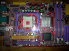
1605861756-soltek.png

This is a small motherboard from a Soltek QBIC Shuttle Clone.

This motherboard has a strange problem.
Once plugged, the motherboard starts, the POST (i can ear the "BEEP") then stops.
I'm not able to start the motherboard using the Power Switches on the motherboard, i have to unplug the power supply and plug it again and...same thing.
Same behaviour without CPU and memory (Power on, POST and power off).

When i'm probing the voltages on the power switch pins, i can see both are receiving 5V, which, to my knowledge, is not normal...

Can you please help me to find what's going wrong with this board ?

Thank you !
Reply 1 of 23, by Horun

User metadata
Rank l33t++
Rank
l33t++

Are you connecting both PSU connectors ? 20pin + 4pin ? Also: some boards will not boot without a good battery, it is rare but I own a few, most are OEM styles of a retail board.

Hate posting a reply and then have to edit it because it made no sense 😁 First computer was an IBM 3270 workstation with CGA monitor. Stuff: https://archive.org/details/@horun

Reply 2 of 23, by parhelia512

User metadata
Rank Member
Rank
Member

Hey, hello Horun, thanks for your answer !

Yes, both connectors are plugged in. with both connectors, and with CPU and memory, the motherboard starts, i can ear the POST beep then shut down.
With only the 20 pin connector and without CPU/memory, the motherboard starts, then stops.
It's acting like the power on pins on the motherboard where shorted...and the voltage on these pins when the motherboard is stopped is the same so there is something that is making a short circuit i think ?

Reply 3 of 23, by parhelia512

User metadata
Rank Member
Rank
Member

It's really strange...i don't understand which component is making the short...There are few scratches at the motherboard back but none seems to cause a short.
Can it be due to a specific power supply required ? I have tested with three different power supply, all ATX ones and the result is the same.
Using a diagnostic board i can see the board posting correctly until it stops... 🙁

Reply 5 of 23, by parhelia512

User metadata
Rank Member
Rank
Member

Hello Chrismeyer6

In fact the board is not hanging, it's just shutting down just after the POST "Beep".
The board is acting like i have the power on switch constantly pushed...starting once plugged then stopping 3 to 4 seconds later...and can't start it using the power on pins...

Reply 7 of 23, by parhelia512

User metadata
Rank Member
Rank
Member

Hello Computerguy08 !

Yes, the board have the same behavior without the CPU. In fact, the board with nothing on it and just the 20 pins power connector is acting the same. Power on, then 3-4s latter, power off (No POST beep of course)

Reply 8 of 23, by computerguy08

User metadata
Rank Member
Rank
Member
parhelia512 wrote on 2020-11-22, 13:20:

Yes, the board have the same behavior without the CPU. In fact, the board with nothing on it and just the 20 pins power connector is acting the same. Power on, then 3-4s latter, power off (No POST beep of course)

Yeah, at this point it's either the board or the PSU that's bad.
If you already checked for shorted components, broken traces and tried a good PSU, I can only suggest a southbridge rework with a heat gun. Otherwise, that board is dead.

EDIT: If the board still does not respond to the PWRON header, it's clearly a board fault.

Reply 9 of 23, by parhelia512

User metadata
Rank Member
Rank
Member

Yes, it's clearly a board problem.
What king of bad electronic component can make the power on circuit always closed ?
I don't know where i should search ? Near the 20 pins connector ? Near the southbridge ?

Thanks for your help !

Reply 10 of 23, by computerguy08

User metadata
Rank Member
Rank
Member

Check the area near the front panel header, you might be lucky and find a shorted/damaged component there.

From an electrical perspective, how is the PWR_ON header presenting ? Both pins shorted ?
Here is a header from another s478 Soltek board, you should have one of the pins tied to 5V:

Capture.PNG
Filename
Capture.PNG
File size
20.88 KiB
Views
622 views
File license
Public domain

Reply 12 of 23, by parhelia512

User metadata
Rank Member
Rank
Member

i'm turning crazy with this board...

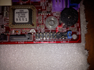
1606069798-photo3995.png

I can have the board working shorting the two pins on the picture.
If i short these two pins :
- The board won't start as soon as power supply is plugged
- If i short the regular power on pins, the board won't start
- If i remove the jumper from these pins, the board start and i have to put them back rapidly beforce the board stops.
- Then the board is working flawlessly

Can somebody tells me what's happening ? I would like to correct this problem to put this board in my case as this is not really convenient to have it working this way:D

Reply 13 of 23, by quicknick

User metadata
Rank Oldbie
Rank
Oldbie

From computerguy08's photo I deduce that in normal operation an ATX board powers on by momentarily pulling up a pin, but your board somehow has this thing reversed. I can almost bet the PLED pin is a ground, and now you keep pulling down the "power-on" pin, so the board starts when you momentarily break the contact (but have to put the jumper back on, because otherwise it's like keeping the button pressed for more than 4 seconds - the board stops).

There are some power switches that also have a normally closed contact, so it's not impossible to use the board thay way although I agree it isn't a proper repair 😀

As for what might be causing this, I'm at a loss. You said something about scratches - check if one of them isn't deep enough to break a connection or cause a short-circuit. I don't know much about the power-on circuitry on ATX boards, but they must be a bit more complicated than just a trace from the header going to the southbridge, because there are also other wake-up sources (LAN and timer come to mind).

Reply 14 of 23, by parhelia512

User metadata
Rank Member
Rank
Member

Hello quicknick and thanks for your message.

Scratches don't seem to be deep enough to break a track nor making a short-circuit but i'm not 100% sure.

I've just found the motherboard manual and here is the front panel...seems normal to have 5V on both power-on pins ? I'm not sure to understand correctly what they are saying concerning the power on switch ?

1606072141-frontpanel.png

Reply 15 of 23, by quicknick

User metadata
Rank Oldbie
Rank
Oldbie

The text below the diagram is a standard one, present in one form or another in every ATX board's manual. It just describes how the switch works (power on or soft-off when pressed and released, force power off when held for >4s).

Having 5v on both pins is not normal, and it's the reason your board doesn't behave as expected. I would venture to say that PWRBT is connected to 5v (either directly or through a resistor), and PWRBT# is the pin that "expects" a 5v pulse for the board to power on, but for whatever reason you already have those 5 volts on that pin. So it works (kind of) normally when you jumper it to the PLED- pin which is a ground. Maybe some pull-down resistor connected to that pin is damaged, you can try installing a 1Kohm resistor between PWRBT# and ground and see if the board starts working as intended. If not, decrease the resistor to 470 or 220 ohm but don't go lower than that.

Reply 16 of 23, by parhelia512

User metadata
Rank Member
Rank
Member

Thanks for your explanation quicknick...was wondering the meaning of "Soft-off" switch...but i understood that it was opposite to the AT switch.

Ok, so you think it's not normal to have 5v on both pins. I was thinking for a moment that maybe the front panel connector was a special one in the original case (which i don't have).

Do you think i can try installing this resistor between the PWRBT# and the LED- pins ?
Can following the track from PWRBT# can help me finding the bad component (and how can i follow the track ?)

Thanks for your help ! 😀

Reply 17 of 23, by computerguy08

User metadata
Rank Member
Rank
Member

Yeah, I was thinking the same as quicknick, the board expects PWRBT# to be tied to GND in normal operation and only when you would normally push the power button it gets pulled to 5V. A pull-down resistor should do the trick.

LED- may not be GND, make sure its tied to GND when the board is unplugged.

You should measure the voltage at the PWRBT# pin after the resistor mod to make sure its closer to GND than 5V.

Reply 18 of 23, by parhelia512

User metadata
Rank Member
Rank
Member

Thanks computerguy08.

To find GND, is it correct to :
- Connect the black probe to the USB shield for example
- Adjust my multimeter in the Ohm mode
- Search with the red probe a point on the motherboard that is connected to the USB shield (no resistance)

Sorry, my electronic knowledge is more Grounded than my PWRBT# !