VOGONS


First post, by RetroSpector78

User metadata
Rank Member
Rank
Member

Hi,

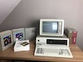
I have an old Philips 286 laptop that had a dead Dallas RTC chip.
The CMOS tests failed and I couldn't setup the system (always started with default settings and couldn't persist anything in the BIOS).

Replacing the Dallas RTC chip was a bit of a botch job ... It was very difficult to remove, and I think I damaged some pads / vias along the way.

Initially the result was a dead laptop. Knowing really well I screwed up on the Dallas RTC I decided to look at the traces.

I had put in place an IC socket for the Dallas RTC chip, and I get the same behavior with the original Dallas RTC chip that was in there.

The Dallas RTC chip is getting power (5V) .

The PCB is multi-layered so I cannot trace al of the connections, but I did notice that on the Dallas RTC A01 and A03 were not connected.

where-as I could verify the following connections (continuity check):

  • Dallas RTC A00 was hooked up to Bios EEPROM D0
  • Dallas RTC A02 was hooked up to Bios EEPROM D2
  • Dallas RTC A04 was hooked up to Bios EEPROM D4
  • Dallas RTC A05 was hooked up to Bios EEPROM D5
  • Dallas RTC A06 was hooked up to Bios EEPROM D6
  • Dallas RTC A07 was hooked up to Bios EEPROM D7

So I hooked up

  • Dallas RTC A01 was hooked up to Bios EEPROM D1
  • Dallas RTC A03 was hooked up to Bios EEPROM D3

Progress ... When I turn on the laptop now, I get orange lines on the LCD, and

- 1 long beep, followed by 3 short beeps
- 1 beep
- 1 long beep, followed by 2 short beeps

The BIOS is an Award BIOS. So this seems to suggest an issue with the video card.

Now most likely there are still some broken traces on the Dallas RTC.

For example I cannot find the connections for

  • pin 14 AS
  • pin 15 RW
  • pin 16 RESET
  • ping 23 SQW

I also don't know if hooking up A01 -> D1 and A03 -> D3 is correct (seemed to make sense and I did get something on the screen and some beeps).

How would I go about debugging this further ? Is there some kind of reference design how these Dallas RTC chips are wired into the BIOS chips, and where the above pins might end up going ?

Do these beeps give any hint on what the issue might be ? I only touched the pads of the Dallas RTC so I wasn't anywhere near the video card.

Reply 2 of 15, by weedeewee

User metadata
Rank l33t
Rank
l33t

Probably still something with the address lines.

Right to repair is fundamental. You own it, you're allowed to fix it.
How To Ask Questions The Smart Way
Do not ask Why !
https://www.vogonswiki.com/index.php/Serial_port

Reply 3 of 15, by RetroSpector78

User metadata
Rank Member
Rank
Member
weedeewee wrote on 2021-04-15, 18:22:

Probably still something with the address lines.

Do you know if there is some kind of reference design in older pcs ? For example the address lines being hooked up to the bios eprom chip in a certain way (direct connection I assume), or how the other pins that I’m currently unsure about would be wired up ?

Reply 4 of 15, by RetroSpector78

User metadata
Rank Member
Rank
Member
majestyk wrote on 2021-04-15, 17:51:

Pin 16 (RESET) is typically connected to Vcc.

There was no continuity with vcc, but I did measured the pin via the socket (without the dallas chip inserted) and it measured 5v.

But I can imagine that such a circuit isn’t that complicated in the actual way it is hooked up to the bios eprom and other components. But the multilayered board makes it difficult to track down the paths.

Reply 5 of 15, by weedeewee

User metadata
Rank l33t
Rank
l33t
RetroSpector78 wrote on 2021-04-15, 19:01:
weedeewee wrote on 2021-04-15, 18:22:

Probably still something with the address lines.

Do you know if there is some kind of reference design in older pcs ? For example the address lines being hooked up to the bios eprom chip in a certain way (direct connection I assume), or how the other pins that I’m currently unsure about would be wired up ?

Not that I know of.
I was thinking that since you had trouble desoldering it and might've damaged pads/vias it could be that maybe some thru hole plating also got damaged and now the top pad and bottom pad are no longer connected.

You could do a live stream, trying to fix it.

Right to repair is fundamental. You own it, you're allowed to fix it.
How To Ask Questions The Smart Way
Do not ask Why !
https://www.vogonswiki.com/index.php/Serial_port

Reply 6 of 15, by RetroSpector78

User metadata
Rank Member
Rank
Member
weedeewee wrote on 2021-04-15, 19:46:

Not that I know of.
I was thinking that since you had trouble desoldering it and might've damaged pads/vias it could be that maybe some thru hole plating also got damaged and now the top pad and bottom pad are no longer connected.

You could do a live stream, trying to fix it.

The way I checked it is by checking from the continuity from the top of the IC socket (where the Dallas is inserted) to whatever target pin I could find (ex: the address lines on the eprom chip).

Was wondering if getting the beep code for video is related to the Dallas chip, and or if I should focus on the video chip.

Reply 8 of 15, by RetroSpector78

User metadata
Rank Member
Rank
Member
Schule04 wrote on 2021-04-16, 02:36:

Please post pictures of the original and the "new" Dallas chips

First tried with the DS12887A but then I heard that there might be compatability issues with those.
Then I tried the DS12887+

2021-04-17 15.48.43 copy.jpg
Filename
2021-04-17 15.48.43 copy.jpg
File size
1.18 MiB
Views
839 views
File license
CC-BY-4.0

Both gave the same result.

  • 1 short beep (when I flip the power switch - keyboard LEDs flash)
  • pause
  • 1 long beep - 3 short beeps
  • pause
  • 1 long beep (keyboard LEDs flash)
  • pause
  • 1 long beep - 2 short beeps (with the original DS1287 the 2 short beeps are a bit shorter)

Got some extra picture (before and after) here : https://drive.google.com/drive/folders/1xMmg5 … 37C?usp=sharing

These beep codes seem to indicate a video issue but I wasn't near the video circuitry (that I know of).
Wonder if a faulty dallas rtc circuit could cause this.

Reply 9 of 15, by weedeewee

User metadata
Rank l33t
Rank
l33t

Guess you'll just have to mod the original DS1287 with a battery.

Could make a nice short video.

Right to repair is fundamental. You own it, you're allowed to fix it.
How To Ask Questions The Smart Way
Do not ask Why !
https://www.vogonswiki.com/index.php/Serial_port

Reply 10 of 15, by RetroSpector78

User metadata
Rank Member
Rank
Member
weedeewee wrote on 2021-04-17, 17:45:

Guess you'll just have to mod the original DS1287 with a battery.

Could make a nice short video.

Does the same thing with the original DS1287 unfortunately.

Guess I broke something during desoldering.

Reply 11 of 15, by weedeewee

User metadata
Rank l33t
Rank
l33t
RetroSpector78 wrote on 2021-04-17, 18:15:
weedeewee wrote on 2021-04-17, 17:45:

Guess you'll just have to mod the original DS1287 with a battery.

Could make a nice short video.

Does the same thing with the original DS1287 unfortunately.

Guess I broke something during desoldering.

Well, from the photo... RP2 doesn't seem to be in a wonderful condition.

Right to repair is fundamental. You own it, you're allowed to fix it.
How To Ask Questions The Smart Way
Do not ask Why !
https://www.vogonswiki.com/index.php/Serial_port

Reply 12 of 15, by RetroSpector78

User metadata
Rank Member
Rank
Member
weedeewee wrote on 2021-04-17, 18:19:

Well, from the photo... RP2 doesn't seem to be in a wonderful condition.

Noticed that also, replaced it with another one but got same issue. (Without the resistor network it only gave the first long beep - 3 short beeps so it does seem to have a purpose of in terms of booting the PC)

Reply 13 of 15, by maxtherabbit

User metadata
Rank l33t
Rank
l33t
RetroSpector78 wrote on 2021-04-17, 18:15:
weedeewee wrote on 2021-04-17, 17:45:

Guess you'll just have to mod the original DS1287 with a battery.

Could make a nice short video.

Does the same thing with the original DS1287 unfortunately.

Guess I broke something during desoldering.

Sorry this happened but learn from the experience and order a proper vacuum desoldering tool. I love the ZD-915 for a cheap option. No one should be attempting to desolder DIP packages on a multilayer board without one

Reply 14 of 15, by megatron-uk

User metadata
Rank Oldbie
Rank
Oldbie

Seconded.

The machines are great - they're fast to use, which means that you don't have to hold your soldering iron on the board/traces/pins for any significant length of time and therefore greatly reduce your chance of damaging the board or components. For through-hole stuff you can't beat them for the price.

I struggled with desolder braid and the manual solder suckers for years until my wife bought me a ZD-915 (or the "Duratool" UK branded equivalent) as a christmas present one year; it's absolutely brilliant.

My collection database and technical wiki:
https://www.target-earth.net

Reply 15 of 15, by hasat

User metadata
Rank Newbie
Rank
Newbie

Have you tried reset internal memory in Dallas chip? Maybe it's content is somehow messed up and prevent notebook from starting. I think this notebook don't have jumper for CMOS memory reset, so you must force reset manually. It's on pin 21, but only models with "A" letter (for example DS12887A) on the end have this function.
From datasheet:
Active-Low RAM Clear. The RCLR pin is used to clear (set to logic 1) all the
general-purpose RAM, but does not affect the RAM associated with the RTC. To
clear the RAM, RCLR must be forced to an input logic 0 during battery-backup
mode when VCC is not applied. The RCLR function is designed to be used
through a human interface (shorting to ground manually or by a switch) and not
to be driven with external buffers. This pin is internally pulled up. Do not use an
external pullup resistor on this pin.