It's reliable enough for me as it is. I have other stuff in that same script that starts sending messages to the LCD with a slightly longer delay, so I know that when the LCD lights up first time after boot, munt is ready. I tested it with about 20 reboots.
Also, I'm an old-style Unix guy and prefer startup scripts to inscrutable binaries. Never got the hang of systemd. My daily driver OS is Gentoo. 😀
OK, the next problem I have is that aconnect refuses to connect ttymidi to mt32d. Even when running as root, it says it's forbidden. In this particular case, mt32d makes a 128:0 output port, and ttymidi makes a 129:1 input port.
But 'aconnect 129:1 128:0' refuses to work. Both ports are listed correctly with aconnect -l.
I/O, I/O,
It's off to disk I go,
With a bit and a byte
And a read and a write,
I/O, I/O
Ah crap it should have been 129:0 not 129:1. The wording of "input" and "output" in alsa-speak is a bit confusing.
aconnect 129:0 128:0 works
I'm happy to say that mt32d works really well on this rock64 (testing with only playing midi files locally to it with aplaymidi). Wile playing, I get loads of around 40-45% on 1 core only with no extra load on the other 3 cores.
Now, for the real test which will be: PC via MIDI port on soundcard > serial port on Rock64 > ttymidi > mt32d > USB sound card, I just need a confirmation of the correct parameters to use for the serial port and ttymidi. The baud rate should be 31250, correct? The standard MIDI baud rate. Not the "serial MIDI" baud rate of 38400 because I'll be using a standard MIDI output, not a serial port through SoftMPU. Although that may be also an option eventually.
(edit) grrr, I can't set the serial speed to 31250. Setserial doesn't work on the rock64 with USB/serial converters (such as /dev/ttyUSB0) it returns a "inappropriate ioctl for device". And stty refuses to accept 31250 as a valid baud rate. It does accept 38400. The USB/serial converter is a cp2102. If I can't find a way to get the correct baud rate on this, I may have to go to the serial>serial route with softmpu and 38400baud.
I/O, I/O,
It's off to disk I go,
With a bit and a byte
And a read and a write,
I/O, I/O
Anyway, here is my current configuration that automatically starts MIDI input at 38400 on usb-serial and connects it to mt32d. All the delays were introduced on purpose because I have run into issues if programs run too quickly one after another at boot. This works correctly.
If I ever find a way to change the speed to 31250, I will incorporate that in the script.
I would appreciate it if someone can point me to a USB/serial converter that supports changing the baud rate to 31250, or at least doesn't give errors with setserial (because I think I can use setserial to force that rate or something close to it - but the CP2102 doesn't work with setserial)
I/O, I/O,
It's off to disk I go,
With a bit and a byte
And a read and a write,
I/O, I/O
As I posted on the previous page, I use a Rock64 from Pine64. It's a very capable board, and I was able to purchase several of them very cheaply (about 1/5 of the price of a Pi4). They are well supported by Armbian, but not projects like MT32-Pi, thus my making of a custom solution. Since the last post I've added Fluidsynth for GM support. The only problem remaining to solve for phase 1 of my project is the baud rate. I'll try a couple other types of USB/serial converters and see if those behave better.
Phase 2 will be adding LCD support. These boards all came with 16x2 LCD displays attached (and cases) and I have a lcd1602 library already installed and can display messages.
But first I want to get the basic MIDI functions down. I want to turn one of them into a complete standalone sound module, which I can attach not only to a computer but also to other MIDI controllers such as keyboards etc.
I/O, I/O,
It's off to disk I go,
With a bit and a byte
And a read and a write,
I/O, I/O
A possibility that just occurred to me if I can't solve the baud issue, is making a simple Arduino baud rate converter. Either use a board with 2 hardware serial ports (like ESP8266 or ESP32) or a regular Arduino using the one hardware UART and one software UART. The software would be very simple, read a byte from one port at one baud rate, and put it out on the other port at a different baud rate. And the Arduino could get its voltage supply from the USB/serial converter (I've done that many times).
i.e. read at 31250baud from PC MIDI port -> send at 38400 baud to the module through serial/USB adapter. Or even skip the serial adapter altogether, and use Arduino's own serial-over-USB connection. I like that.
A simple modification of this example https://www.arduino.cc/en/Tutorial/LibraryExa … reSerialExample only changing one port from 115200 to 38400 (or even leaving it at 115200 and setting the appropriate baud rate on the Pi side as well) and the other changed from 38400 to 31250. Easy.
1
2#include <SoftwareSerial.h>
3SoftwareSerial midiSerial(2, 3); // RX, TX pins
4
5void setup()
6{
7  // Open serial communications and wait for port to open: this goes to Pi board via USB
8  Serial.begin(38400);
9  while (!Serial) {
10    ; // wait for serial port to connect. Needed for Native USB only
11  }
12  // set the data rate for the SoftwareSerial port
13  midiSerial.begin(31250);
14}
15
16void loop() // send data received at soft serial port at 31250baud to hardware serial over USB at 38400
17{
18  if (midiSerial.available())
19    Serial.write(midiSerial.read());
20}
this is e.g. for an Arduino Nano. Will need to make a little adapter board with optocoupler for the Arduino.
(edit) ugh I forgot the Pi boards run at 3.3V and arduinos at 5V... will have to reconcile them somehow. 😀
(edit2) That is actually not a problem at all. The USB ports on the Rock64 (and all Pis) work at 5V, and that supplies the required voltage for the Arduino. There will be no other connection from the Arduino to the SBC except through USB, so that is fine.
Please be careful with Sharp PC-900, though.
It was a faulty, non pin-compatible copy of the lesser known H11L1..
What's good, though, both have a Schmiddt trigger circuit.
"Time, it seems, doesn't flow. For some it's fast, for some it's slow.
In what to one race is no time at all, another race can rise and fall..." - The Minstrel
Jo22wrote on 2021-08-29, 07:37:Please be careful with Sharp PC-900, though.
It was a faulty, non pin-compatible copy of the lesser known H11L1.. […] Show full quote
Please be careful with Sharp PC-900, though.
It was a faulty, non pin-compatible copy of the lesser known H11L1..
What's good, though, both have a Schmiddt trigger circuit.
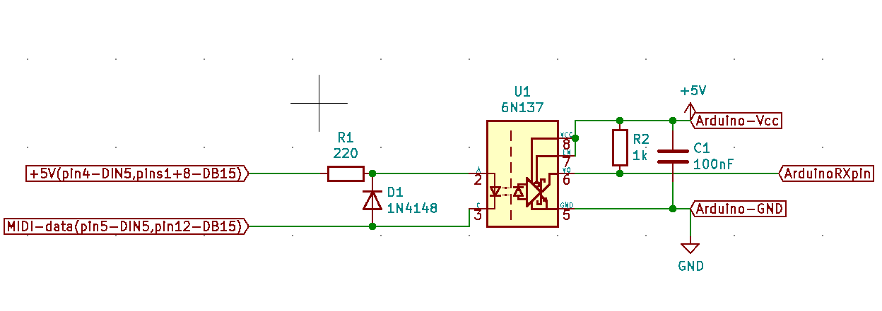
haha no I don't have a PC900. I will be using a 6N138 in the Bob Pease configuration (which is why I linked to that article)
Alternatively, I have a few 6N137 on the way as well - those are also Schmidt trigger-based and have great response times (tens of nanoseconds, vs. max 2 microseconds required by the MIDI specification) and are rated up to 10 Mbaud. https://www.vishay.com/docs/84732/6n137.pdf
I actually don't have either in hand right now, all I have is some H11F1 but those are horribly slow for this application, and cannot be sped up by any tricks. https://www.onsemi.com/pdf/datasheet/h11f3m-d.pdf
I think I'll make a small PCB for this, solder it directly on top of the Arduino, together with a DB15-male connector (and why not, also a DIN5 connector - this way one could also use it by plugging a MIDI cable into it) and place it all in a small 3d printed box. The box would get plugged into the sound card's DB15 and at the other end connected to the SBC by an USB cable.
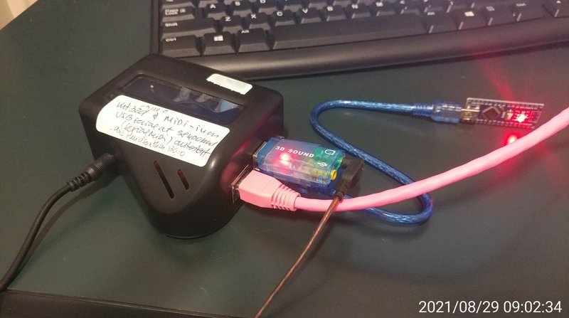
And here's a pic of the setup as it is right now. The SBC is inside the box with the display (display currently not in use), with network cable (for ssh access), sound card and arduino plugged in. There's one more USB port available.
I/O, I/O,
It's off to disk I go,
With a bit and a byte
And a read and a write,
I/O, I/O
I just had a crazy idea about the MIDI-to-Pi-through-Arduino interface.
The optocoupler used in the classic schematic performs 2 functions:
1. completes the current loop of the MIDI source (because whatever is connected to the MIDI signal needs to be able to source 5mA from +5V per the spec), and
2. maintains the phase of the signal, i.e. input=0 -> output=0, and input=5V -> output="high"
The "standard" use for an optocoupler, to isolate from high voltages, is not really a factor. Or else, they would be used for all sorts of other peripherals: joysticks, mice, keyboards, all USB devices etc. - and they're not.
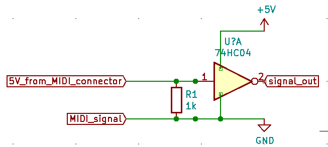
So then, can the interfacing be done in a different way that still respects points 1 and 2 above? I mulled it for a bit and came up with this crazy circuit.
Yes, the MIDI signal is connected to the ground of the inverting buffer, and the input of the buffer is connected to the 5V pin of the MIDI connector. The 5V from the MIDI connector is NOT connected to the 5V that supplies the inverter (and which comes from the following stage, in this case the Arduino)
The resistor acts as a voltage/current converter, and closes the MIDI current loop at 5mA. The buffer input follows the voltage across the resistor, which is inverted with regard to the MIDI signal. Then the inverter inverts it again, so the output is in fact in phase with the MIDI signal.
One advantage of using this over the optocoupler method is that an inverter is much faster than the optocoupler. Datasheets show transition times of 15-20ns, which is way less than the 2us that the spec asks for - and which optocouplers have trouble meeting. Also, reduced number of components and size of pcb; one resistor and one SOIC package is all that's used. 😀 And the CMOS inverters are extremely easy to find and cheap.
I/O, I/O,
It's off to disk I go,
With a bit and a byte
And a read and a write,
I/O, I/O
I have found a project that can make this whole interfacing even simpler. It uses a generic USBASP programmer, which is reprogrammed with custom firmware to transform it into a USB audio interface that accepts directly MIDI data: https://dragaosemchama.com/en/2018/10/usbasp- … a-midi-adapter/
Still needs an optocoupler on the input.
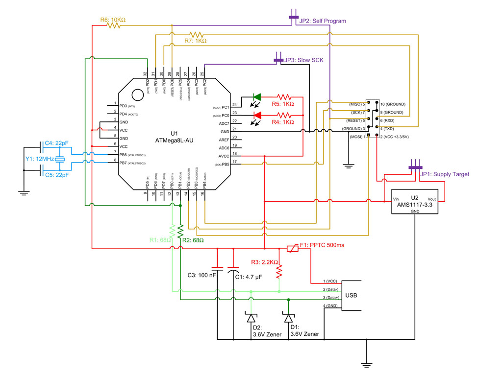
Since I had a couple of USBASP devices (you need a second one to program the first one) I flashed one of them. One caveat is that before you do that, you have to edit the project makefile to set the correct fuse bits for the microcontroller that the USBASP uses, in this case an AtMega8. The bits that need to be set (near the top of the makefile) are FUSE_L = 0x9F and FUSE_H = 0xC9
Then with the devices connected one to the other, you run 'make program" in the folder that you clone from github https://github.com/robsoncouto/usbaspmidi and it will program the device. You may need to install avrdude on the computer you do this on if you don't have it. I actually did it directly on the Pi.
Then you disconnect the 2, take the one you programmed and insert it into the Pi, and it registers with alsa as USBASP-MIDI; you can then use aconnect to connect it to the mt32d input.
Now, mt32d accepts imputs both from ttymidi (which can be used to send data over a USB-serial adapter from a PC through the serial port using SoftMPU for instance) and from USBASP-MIDI that will accept data from a standard MIDI output on PC.
This is a simpler and more elegant solution than the one I was working on earlier, and should work on a real Pi, any of the clones as well as a regular PC. The USBASP devices can be found for under $4 on sites like Amazon and ebay. You need to select ones that have jumper headers for J2 (that needs to be closed to reprogram it) or at least have solder pads for J2 where you can solder a 2-pin header. Some devices sold don't have either.
(edit) there are several hardware revisions of the USBASP floating around. I looked through mine, and I have 2 types:
1. blue PCB, labeled "USBASP V2" and have jumpers, these are OK to use as the relevant pins from the MCU are brought to the 10-pin interface (pin 4: TxD, pin 6: RxD). Schematic: http://www.actuino.fr/wp-content/uploads/usbasp-sch.jpg
2. black PCB, no revision marked and have no jumpers at all. These are NOT OK to use to be flashed to USBASP-MIDI because pins 4 and 6 on the connector are tied to ground, not TxD/RxD. They can be used for flashing other devices though.
So beware when you buy.
I just whipped together an optocoupler interface, connected it to the USBASP-MIDI and to the Rock64SBC, with input from my Win98 box through the sound card midi out. It works. I made a quick and dirty video of it playing music during the Dune2 intro. The speakers you hear are connected to the SBC's sound card, not to the computer.
(edit) I am getting some stuck notes occasionally, and I think it may be because I am overdriving the LED in the optocoupler. A 220 ohm resistor as is found in most schematics (and which I used) will give the LED about 15mA of current and that may oversaturate the receiver, degrading the tPHL. When I make another one I will try higher values for that resistor, I have a feeling that something between 400-600 ohms may work better.
I/O, I/O,
It's off to disk I go,
With a bit and a byte
And a read and a write,
I/O, I/O

