First post, by User5518
- Rank
- Newbie
Hi everyone,
First, a little story:
Today I drove over 350 km (round trip) to pick up a Siemens Nixdorf PCD 4ND. I bought it on kleinanzeigen.de, and from the pictures, it appeared to be in excellent condition. When I arrived, I was greeted by an elderly couple, and the PCD 4ND was already set up for testing on their living room table. Unfortunately, I immediately noticed a few issues:
- A red vertical stripe ran through the display.
- The floppy drive couldn’t read any disks.
- Windows 3.11 threw a “System Error” and wouldn’t boot.
The red stripe bothered me the most. However, the sellers knocked 20 Euros off the price, so I ended up taking the device with the following specs (and defects) for 80 Euros:
- 486D4 with 75 MHz
- 4 MB RAM
- 500 MB hard drive
- SoundBlaster-compatible sound card
- Active Matrix TFT display (not STN) – but with a red stripe. 😒
This evening, I sat down to address the individual problems.
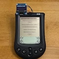
When I turned the device on, this is what I saw:
For some reason, the stripes multiplied during transportation. 🙁
So, I decided to work on the floppy drive first before attempting the display. The floppy drive (which internally is a "Citizen LR102061") luckily just had a worn-out drive belt. My replacement belt doesn’t fit perfectly, so disks aren’t always read reliably, but at least I could boot DOS form a floppy.
Now, onto the display. I disassembled it and noticed that when I gently ran a screwdriver along this part:
The stripes flickered.
It became clear to me that soldering something here was out of the question. So, I decided to try using hot air.
I started with 250°C and planned to slowly increase the temperature if nothing happened.
When I applied the heat gun, more stripes initially appeared, but after cooling down, they disappeared:
I’m super happy!
Of course, I don’t know yet if this is a permanent or just a temporary fix, but I’m very pleased that it’s working for now and that I essentially have a fully functional PCD 4ND. 😀
Has anyone else ever repaired display stripes this way and can tell me how long this solution might last?
Best regards,
User5518
