VOGONS


First post, by thingsforjason

User metadata
Rank Newbie
Rank
Newbie

Hello all! Hopefully the links below don't cause this post to drop into forum jail.

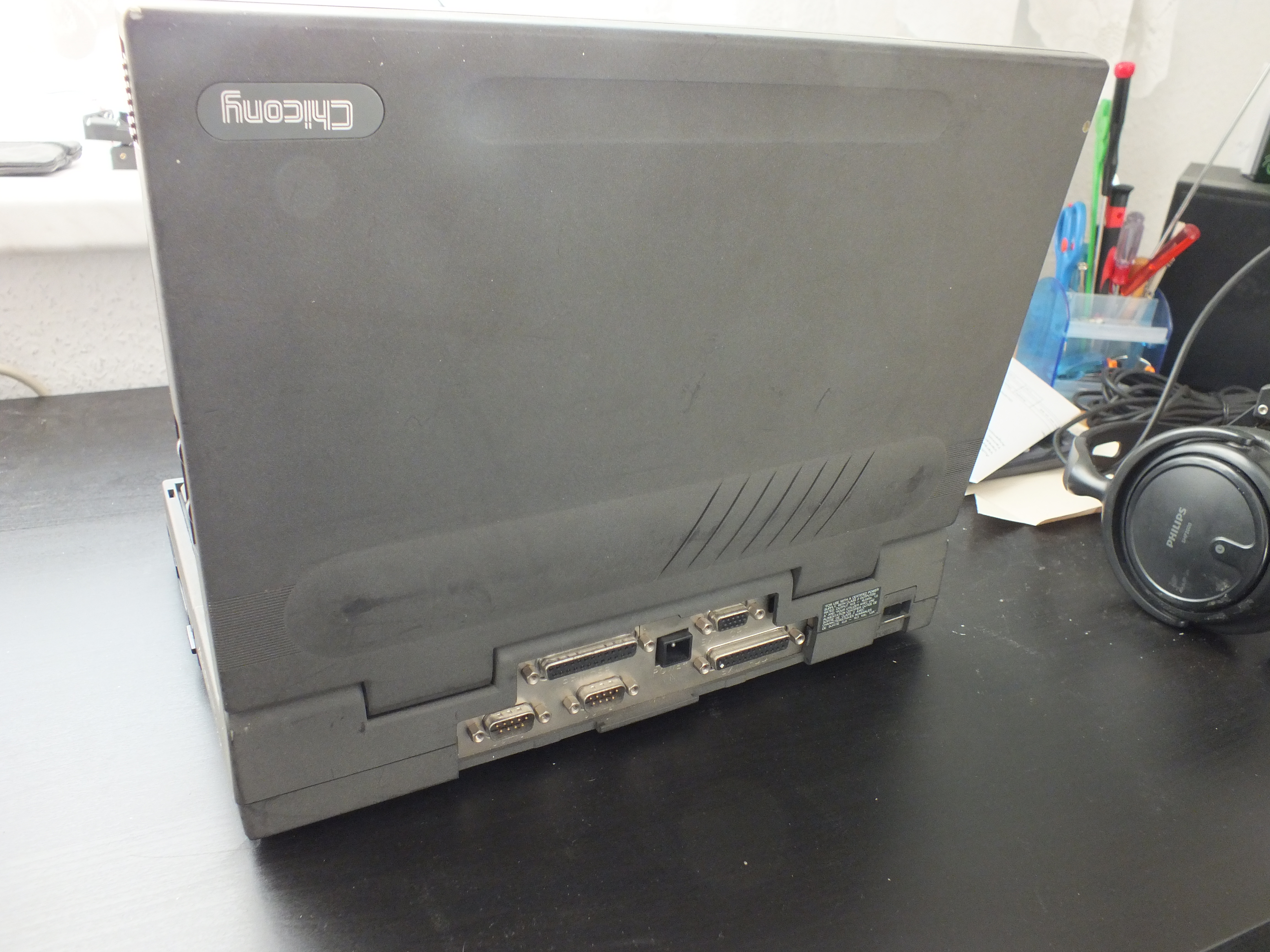
I'm the proud recipient of a good condition Chicony NB5620, but unfortunately the power supply is missing. It's listed as a 10.8-16.5VDC 1.8A power supply but is a proprietary 3 pin connector. Does anyone have some guidance on sorting out the pinout short of disassembling the whole thing? There's three pins too, which is a little confusing for me. I'd be okay with disassembling the old NiCad as well if that's a possible solution for identification. The pins are some thicc boys (~2mm) but I'm hoping I can rig something with generic crimp sockets and heat shrink, once I get the pinout sorted.

More info on what I acquired:

http://www.jubatian.com/articles/chicony-nb5620/
https://macdat.net/laptops/chicony/nb5620.php

Reply 1 of 4, by Horun

User metadata
Rank l33t++
Rank
l33t++

Hmm from first link:
"Some wicked design idea back then mixed up the wire colorings: the standards tell (what you can except from the PC fan as well) that the red wire carries the positive voltage, while the black is the ground. Here although the black wire is properly attached to ground, the red is not carrying the voltage. Carefully examining the board will reveal that the red and the black wires share the same voltage (0V). The power (16.5V) is carried by the yellow (!) wire. "
So the 3 pins are Gnd, Gnd and +16.5v. Using a ohm meter you should be able to find which pins are ground checking each pin to the metal back. Those of 0 ohm be ground, the one with higher resistance should be the +V
https://macdat.net/images/laptops/chicony/nb5620/back.jpg

Hate posting a reply and then have to edit it because it made no sense 😁 First computer was an IBM 3270 workstation with CGA monitor. Stuff: https://archive.org/details/@horun

Reply 2 of 4, by thingsforjason

User metadata
Rank Newbie
Rank
Newbie

Thanks for reading more thoroughly than I did!

Tested with a meter and added a markup for future reference. Looking at the back, the top pin and right pin are ground, and also have continuity with the metal back plate. That leaves the pin on the left to be the voltage pin, but I'll find out when I get some sockets that hopefully fit.

Reply 3 of 4, by thingsforjason

User metadata
Rank Newbie
Rank
Newbie

And a few hours of fiddling later, we have a plug! Thanks again!

Reply 4 of 4, by Thermalwrong

User metadata
Rank Oldbie
Rank
Oldbie
thingsforjason wrote on 2025-05-15, 15:59:

And a few hours of fiddling later, we have a plug! Thanks again!

Nice, that's 3d printed? Did you use springs for the contacts? that should have a really good contact surface.

To do similar with mine I've used some gold plated 2-leg socket pins which are wrapped in heatshrink then placed onto the pins. To make the shape of the connector I melt down some black thermoplastic (blackmorph) pellets on the hotplate and then jam that plastic into the connector, pushing it in so it doesn't get airgaps. That's my quick way to make weird connectors since the heatshrink stops the plastic going into the pins that matter and once cooled, the connector usually comes out without sticking to the DC jack and the molded version has the keying features 😀

I harvested those socket pins off of a dead industrial PC board that used 3 or 4 row 2.54mm board-to-board connectors, taking the pins out from the female connector. Apparently that's called a DIN 41612 Connector, nice gold plated contacts on the female socket parts that's pretty good for making bespoke DC jacks with.