VOGONS


First post, by mario24v

User metadata
Rank Newbie
Rank
Newbie

Howdy,

Have this Enhance Electronics AT power supply that I bought with an Escom case. I started replacing the capacitors with good ones and when I was about finished I saw that I have a missing resistor, signs show that it was ripped. How, why and when, can't imagine. Trouble is that of course, I cannot find the schematic.

Type is Enhance Electronics P520.
Missing resistor is R25.
R22 seems to be 210 ohms, R23 130 kOhms, R24 3.3 kOhms all +/- 5%. That if I read it right. What could be the value of R25?

Thanks so much!

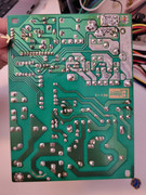
Back of the power supply board (R25 position marked with white):
enhance-back.jpg
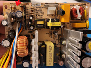
Front: (R25 position marked with red):
enhance-front.jpg

Compaq Portable I
Compaq Prolinea 4/50
IBM PS2 286
Amiga 1200hd and other custom goodies

Reply 1 of 5, by PD2JK

User metadata
Rank Oldbie
Rank
Oldbie

Could be snipped away on purpose, i.e. different configurations for regions or power delivery.

i386 16 ⇒ i486 DX4 100 ⇒ Pentium MMX 200 ⇒ Athlon Pluto 700 ⇒ AthlonXP 1700+ ⇒ Opteron 165 ⇒ Dual Opteron 856

Reply 2 of 5, by MikeSG

User metadata
Rank Oldbie
Rank
Oldbie

As above it's possible R25 is a factory modification for 240-250v.

Enhance Electronics is a USA based company, where the standard is 120V.

It's worth finishing the recap and testing all output voltages are correct.... Or looking up the schematic for the voltage regulator nearby and seeing what it uses R25 for.

Reply 3 of 5, by mario24v

User metadata
Rank Newbie
Rank
Newbie

It was initially there as its feet are still there, they are soldered, only the body is missing somehow. I would measure if I'd know what. I can see it has 4 transistors (one group of two of same type - on the right - and one group with a smaller one and a bigger one - on the left of the picture).

Compaq Portable I
Compaq Prolinea 4/50
IBM PS2 286
Amiga 1200hd and other custom goodies

Reply 4 of 5, by HwAoRrDk

User metadata
Rank Newbie
Rank
Newbie

I agree, could well be either a production mistake (part stuffed when it shouldn't have been) that was rectified afterwards, or an intentional post-production modification.

Plus, if someone was going to steal a resistor, they likely would unsolder it rather than cut it off, because they would want the legs present for re-use.

Looking at the circuitry R25 is attached to, it appears to be in parallel with R23 & R24, with one side of them all connected to ground. I suspect it's some kind of lower leg of a feedback divider, and the use of multiple resistors is to make up an uncommon value that a single standard value resistor can't satisfy (130k ∥ 3.3k = 3.218k). And maybe R25 was snipped at the factory as part of a test and adjustment procedure (i.e. remove R25 to alter the combined resistance value).

One thing confusing me though is that the adjacent blue/purple big and little capacitors both have their positive terminals connected to the same ground trace. 😕 Maybe these resistors and caps are something to do with one of the negative voltage rails.

Reply 5 of 5, by TheMobRules

User metadata
Rank Oldbie
Rank
Oldbie
HwAoRrDk wrote on 2026-02-16, 17:14:

Looking at the circuitry R25 is attached to, it appears to be in parallel with R23 & R24, with one side of them all connected to ground. I suspect it's some kind of lower leg of a feedback divider, and the use of multiple resistors is to make up an uncommon value that a single standard value resistor can't satisfy (130k ∥ 3.3k = 3.218k). And maybe R25 was snipped at the factory as part of a test and adjustment procedure (i.e. remove R25 to alter the combined resistance value).

One thing confusing me though is that the adjacent blue/purple big and little capacitors both have their positive terminals connected to the same ground trace. 😕 Maybe these resistors and caps are something to do with one of the negative voltage rails.

I think you are correct on both. Some manufacturers use a trimmer resistor in the feedback divider to adjust the output voltages, others just fine tune the voltages by changing (or removing, like in this case) one of the resistors during testing.

As for the caps having the positive terminals connected to ground, you can see the white and blue cables nearby (-5V and -12V), as well as what is probably a 7905 on its own little heatsink to regulate -5V. So those capacitors are likely filtering the negative rails as you suggested.