VOGONS


First post, by raymangold
User metadata
Rank Member
Rank
Member

Hello,

I'm presently converting an MT-100 'revision 1' board to work in a MT-32 revision 0 chassis. There are actually a fair amount of differences and it appears the power connector to drive the LCD display isn't actively supplying power (Roland left out a few things like resistors and diodes).

--> if no one was aware, the revision 1 MT-32s and MT-100s use the same base board, but depending on its configuration it will have different components soldered in.

Wondering if anyone can provide a fairly decent photo of a revision 1 (not 0) motherboard so I can compare if I'm missing anything on the conversion process. I'm also curious what type of voltage regulator it uses as the MT-100 may be using an excessive one to drive the rest of the MT-100.

Reply 1 of 14, by DataPro

User metadata
Rank Member
Rank
Member

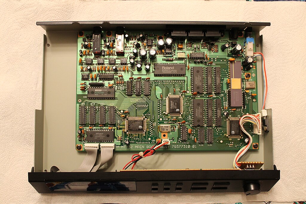
1024px-Roland_MT-32_Oldtype_Revision_1_PCB_View.jpg

HP Vectra 562 P166Mhz/256Ko L2 cache/Triton 430FX - 112Mo RAM - 2x 32Go+64Go CF Card - Matrox G2 8Mo - SB AWE64 ISA (PnP) + Roland MT-32 & M-GS64 (SC-88) & JV-1010 - Nec USB 2.0 PCI - Promise Ultra100 TX2 - Hama multicard reader

Reply 2 of 14, by raymangold

User metadata
Rank Member
Rank
Member

That would be the revision 0 (no headphone jack), looking for a motherboard photo of revision 1 with the headphone jack 😉
Surprisingly enough there doesn't seem to be a photo of one on the entire internet.

Reply 4 of 14, by raymangold

User metadata
Rank Member
Rank
Member
vetz wrote:

I'll see what I can do. Both the MT32's I own turned out to be rev 1 when I received them.

Yeah if you could take a decent photo of the mobo that would be great. This would also allow me to publicly outline the process on converting an MT-100 into a revision 0 MT-32 chassis-- as it seems no one has done this before, or at least talked about it? A fair bit of soldering required, but nothing too complex-- it's good to replace all of the aging capacitors in the process anyways.

One curiosity is that the MT-32s (both revisions) actually use BIPOLAR electrolytics, which is very uncommon to see in digital synthesizers... which means people who complain that the MT-32 is noisy don't realize that Roland actually put effort into it.

The remaining guts will be a sad MT-100 chassis swithout its MT-32 board, and a loose rev 0 board missing its connectors (coincidentally it also happens to have been modded with the 'RealWorld' interface and a backup battery). Not sure what to do with either of them as a rev 0 board can't fit in an MT-100 chassis as it lacks the extra power pads.... well theoretically you could modify it to mimic the power pads by modifying the power section but ehhh.... I don't think anyone would want an "MT-10" (a joke at the fact it would be the first MT-100 with a rev 0 board).

Reply 6 of 14, by DataPro

User metadata
Rank Member
Rank
Member

Sorry for the mistake... the photo was labelled as Rev.1. I forgot to check headphones plug...

I can't photograph mine because it's also and rev.0

HP Vectra 562 P166Mhz/256Ko L2 cache/Triton 430FX - 112Mo RAM - 2x 32Go+64Go CF Card - Matrox G2 8Mo - SB AWE64 ISA (PnP) + Roland MT-32 & M-GS64 (SC-88) & JV-1010 - Nec USB 2.0 PCI - Promise Ultra100 TX2 - Hama multicard reader

Reply 7 of 14, by raymangold

User metadata
Rank Member
Rank
Member
Cloudschatze wrote:

While that does have (somewhat) of a photo, it's repeating things from the solder mask that I'm already aware of. I need a photo of a rev 1 board to confirm what the solder mask isn't clear of in certain areas, and also to determine what components are different from the MT-100 and MT-32 boards. Because the schematic just shows everything which is unhelpful.

I'm also curious to see what regulator a revision 1 MT-32 has. If I had a unit myself I would have long since taken a photo for wikipedia.

Reply 8 of 14, by raymangold

User metadata
Rank Member
Rank
Member

10849970_385833744928809_7115093765342886623_n.jpg?oh=64c62fd9d4a5e591f80ae355994530be&oe=54FB0403

Okay I decided to take a photo of (my) board and explain why I need another photo of a rev 1 MT-32 board.

On the right you'll see the voltage regulator is considerably larger and even has its own PCB with a (filter?) capacitor. Because the PCB wouldn't fit flush against the MT-32 chassis I used some wire to bring the PCB away from the VRM. Just above that is the main power section of the board, it uses I believe considerably larger uF values than a non-MT-100 board (to compensate for the extra power draw of the extra junk at the top of the MT-32 board) and there's also a connector CN7 populated used to send power to the top MT-100 circuitry. To the very far left is an extra connector used by the MT-100, and I had to desolder the headphone audio jack so the MT-32 rev 1 board would fit in the rev 0 chassis.

Finally at the bottom is the power connector for the LCD screen. I am not sure if this is the correct orientation because the solder mask indicator is a bit vague, but I believe that it is (which would mean the orientation is inverted from a rev 0 board).

So I'm not sure if that resistor near the LCD power connector needs to be populated, I'm not sure if I can reduce the uF of the power filter caps and I'm also not sure if I can go back to using the regular VRM as used by a rev 0 MT-32. There may also be other variances I'm not aware of-- which as you can see would all be solved by a simple photo which for some reason does not exist on the entire internet.

And I did change a lot of the capacitors and did extensive solder work on that board if anyone was wondering. Like ALL Roland PCBs it is extremely easy to work on.

Reply 9 of 14, by PhilsComputerLab

User metadata
Rank l33t++
Rank
l33t++

Was your MT-32 modified? I just took some images of a MT-32 (New) and they are uploading.

Reply 10 of 14, by raymangold

User metadata
Rank Member
Rank
Member
philscomputerlab wrote:

Was your MT-32 modified? I just took some images of a MT-32 (New) and they are uploading.

Hey Phil,

That is actually an MT-100 board; prior to my modifications it was missing the majority of the connectors that you now see present. I never bothered to remove the MT-100 specific connectors, so there will be some extra ones as a result.

I purchased an MT-100 and a rev 0 MT-32 to create a discreet rev 1 MT-32-- as at the time there were no rev 1 MT-32s available (of course one did pop up a week later for rather cheap, but since I already bought my parts I opted out).

Since the rev 0 MT-32 I bought ended up having the 'real world interfaces' modification w/ battery, I can write a tutorial to undo those changes if anyone is interested. Because I am also lacking another chassis, I should see about reverse engineering the front LED panel, too.

Reply 11 of 14, by PhilsComputerLab

User metadata
Rank l33t++
Rank
l33t++

Forgot about the images 😊

http://imgur.com/a/Wq6JG

Hope this helps you out...

Reply 12 of 14, by raymangold

User metadata
Rank Member
Rank
Member
philscomputerlab wrote:

Forgot about the images 😊

http://imgur.com/a/Wq6JG

Hope this helps you out...

Awesome thanks Phil!

So for starters:
#1 the old voltage regulator is present in both the Rev 0 / 1 MT-32s. It's just the MT-100 that uses the larger one.
#2 there is indeed a resistor missing, along with two ceramic capacitors and the power section has a few components shuffled around.
#3 the rev 1 boards do have the LCD power connector inverted from the rev 0 boards.
#4 the MT-100 boards are fitted with larger capacitors (which isn't necessary for a stand alone MT-32)

Well, time to get soldering... I'll update here later to see if the conversion is successful (I never tested the board in the MT-100 and have no clue of any reprimands).

Reply 13 of 14, by PhilsComputerLab

User metadata
Rank l33t++
Rank
l33t++

If you need closer images of certain areas just let me know! Happy to help. The unit is really quick to open 😀

I got a MT-100 but it seemed a bit more work to open the unit so I left it.

Reply 14 of 14, by raymangold

User metadata
Rank Member
Rank
Member

We now have power going to the LCD after reworking the circuitry with Phil's photos (and I switched it to use the smaller voltage regulator):
10696364_386260028219514_1271586384433506093_n.jpg?oh=20119c1e35ff4e81df521575528aa0bf&oe=5541769F

Although as I suspected, it powers on with no splash screen or any indication of life. I'm not even sure how well it will operate without its malignant MT-100 top half-- i.e. if it can still respond to MIDI commands. Why is that? Well if we take a look at the BIOS chip, it's not at all like the one on Phil's MT-32, it's shorter and doesn't have a UV window. Circled here:
10857916_386260058219511_5524418110551091606_n.jpg?oh=0a7e903835be431822322953d9eea1bc&oe=550066EB

So it appears these MT-100 boards were flashed with some 'dumber' firmware. I'm going to open the top half of the MT-100 to see what kind of logic is there. UNFORTUNATELY the rev 0 firmware ROMs are different (A B and C chips), whereas this one isn't labeled with a letter. If I can't find a ROM image I might have to buy a rev 1 MT-32 after all (blah!) I would also have to buy a chip programmer-- something that I've been holding off.

EDIT:

So after gutting out the top MT-100 half (and pulling out that weird floppy drive), it appears there's a BIOS chip on the top as per my hypothesis:
10294493_386271378218379_5947161647843418328_n.jpg?oh=a59359b878260e6cd2ae760402046b92&oe=550F1E0E&__gda__=1425696612_188615daf38b3e24a48eae6b64a13935

I'm going to try soldering it in place of that weird one presently on the MT-32 board... I have a feeling that acts as some sort of redirection chip and not a real BIOS.