VOGONS


Reply 300 of 346, by mockingbird

User metadata
Rank Oldbie
Rank
Oldbie

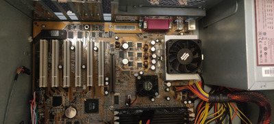
Ok, I did some more testing. I changed the multiplier to 21 at the underside of the motherboard socket pins and set the FSB to 100Mhz via jumpers on the motherboard (testing with a Biostar M7VKD). The system boots at 2.1Ghz and is stable. The purpose was to allow a lower CPU speed (300Mhz), as opposed to running it at 133Mhz FSB (where the minimum system speed was 3 x 133 - 400Mhz).

VIAFSB was mentioned, but VIAFSB is not very useful because it does not allow reducing the FSB from 133Mhz to 100Mhz. It does not work like you think it does on the K7 platform compared to other platforms. For all intents and purposes, it is not very useful for throttling (on this platform).

Also, bear in mind, I am only focusing on processor speed and disabling caches (or the L1 cache only, in our case, because disabling the L2 is not helpful nor possible for that matter) and ignoring other throttling methods because I have found them to be lacking in terms of compatibility with many games (Jazz Jackrabbit, Titus) .

At 500Mhz with L1 disabled (setmul 5 l1d), NSSI puts it approximately on par with a 386 DX/33
At 1.1Ghz with L1 disabled (setmul 11 l1d), NSSI puts it roughly on par with a 386 DX/40

A few things to note:

1) You are only allowed to set multipliers from 3x to 11x (minus 4x, which hangs the system, at least with this configuration). You get access to the half multipliers only after 5x (so 5.5, 6.5, 7.5, etc..., but not that they're useful)
2) The system requires a hard reset after playing with the multiplier (or when I set it to 3x, at least), it won't POST with a regular reboot
3) Going back to the full speed of 2.1Ghz requires a reboot. Setmul will only allow you to set it back up to 1.1Ghz (11x multiplier) when you change it

So all in all, not the most versatile platform for throttling. Certainly better than a lot other platforms out there, but I would prefer something that allowed me a wider range of speed at the low end (486 would be nice). And this concludes my years-long investigation into the K7 platform as a viable platform for retro builds.

edit: Just a small addendum -- The Abit KT7A has a unique PLL (PhaseLink PLL205-03) which does in fact supports 66Mhz FSB. Theoretically, a 200Mhz downclock should then be possible with the K7 (3 x 66), but VIAFSB doesn't actually succeed in setting the 66Mhz ("viafsb pll205-03 66.80 -u") just get's stuck at "Setting FSB...". I think this is a chipset limitation and not a bug or anything with VIAFSB. But this is irelevant for the most part, because K7 does not scale well at all with clock speed increases (or decrases for that matter) once you disable its L1. You can throw hundreds of megahertz at it, but as long as the L1 is disabled, it's consistently about as fast as a 386, except with the added oddities you get from disabling a CPU's L1 cache.

Last edited by mockingbird on 2023-09-03, 22:36. Edited 2 times in total.

mslrlv.png
(Decommissioned:)
7ivtic.png

Reply 301 of 346, by Joseph_Joestar

User metadata
Rank l33t
Rank
l33t
mockingbird wrote on 2023-09-03, 21:18:

So all in all, not the most versatile platform for throttling.

Did you try ACPI Throttle?

It worked pretty well for me back when I was using an AthlonXP build for DOS gaming. From what I recall, I was able to reach 386, 486 and Pentium MMX speeds without too much trouble.

PC#1: Pentium MMX 166 / Soyo SY-5BT / S3 Trio64V+ / Voodoo1 / YMF719 / AWE64 Gold / SC-155
PC#2: AthlonXP 2100+ / ECS K7VTA3 / Voodoo3 / Audigy2 / Vortex2
PC#3: Athlon64 3400+ / Asus K8V-MX / 5900XT / Audigy2
PC#4: i5-3570K / MSI Z77A-G43 / GTX 970 / X-Fi

Reply 302 of 346, by mockingbird

User metadata
Rank Oldbie
Rank
Oldbie
Joseph_Joestar wrote on 2023-09-03, 21:23:

Did you try ACPI Throttle?

It worked pretty well for me back when I was using an AthlonXP build for DOS gaming. From what I recall, I was able to reach 386, 486 and Pentium MMX speeds without too much trouble.

Oh yes sir, I tried it all... ODCM sounded good on paper, but it wasn't very good at all in practice... It's either real hardware for me or throttling by reducing CPU Mhz/disabling CPU features only. Artificial throttling just ain't what it's set out to be.

Oh, and I have a VIA Ezra-T system in the works. Only about as fast as a Celeron 600, but excellent throttling ability on the low end.

mslrlv.png
(Decommissioned:)
7ivtic.png

Reply 303 of 346, by makechu

User metadata
Rank Newbie
Rank
Newbie

Just for throwing some seeds around for some, perhaps dumb, ideas:
Besides slowing down the CPU with multipliers, bus speed, and disabling L1 and L2 cache, I wonder if anyone has tried to somehow increase the RAM latencies to make the system slow down. At least in theory, isn't the next bottleneck after disabling CPU caches the speed of the RAM? Without caches, all the code execution is done via RAM transfers. Then, if it would be possible to increase CAS, RAS, precharge intervals etc. much higher, couldn't it be possible to significantly further reduce the code execution speed?
For this, some program would be required to modify the chipset registers or modifying the BIOS to support some silly latencies that the chipset developers at the time quite likely did not consider, even if it would have been possible at the chipset / CPU level. I don't know how flexible memory controller on the KT133A is, or if this would be even possible by accessing the chipset registers, but this is just a random idea to throw out there... Also, I wonder if there could be some other chipsets / CPUs that makes it possible.

The other idea is, that what if somebody made a PCI card, that just triggers interrupts just for slowing the system down, to force the CPU, or chipset, pointlessly execute interrupt cycles periodically? Many years ago, I was accidentally able to bog down even quite a modern system, by accidentally programming an interrupt to be executed on a pci-bus card at a high rate. Maybe Bus Matering has to be disabled for this to have some consistency, but anyways.

Reply 304 of 346, by luk1999

User metadata
Rank Newbie
Rank
Newbie

VIA KT133A allows very limited control for memory timings. I believe that you can go "down" from 2-2-2 to 3-3-3 for main memory timings. You can also control tRAS (2 or 4 settings) and Bank Interleave (2/4 IIRC). There are some other memory related params, but they don't have significant impact on performance.

Pentium 4 2.4C, ASUS P4C800-E Deluxe, 1 GB RAM, GF FX5700 128 MB AGP, SB Audigy, Chieftec GPS-400AA-101A, Win XP SP2
Celeron 400, Compaq Garry, 128 MB RAM, Voodoo Banshee, ALS100 Plus+, Compaq 200 W, Win 98SE

Reply 305 of 346, by BitWrangler

User metadata
Rank l33t++
Rank
l33t++
makechu wrote on 2023-09-23, 20:52:

The other idea is, that what if somebody made a PCI card, that just triggers interrupts just for slowing the system down, to force the CPU, or chipset, pointlessly execute interrupt cycles periodically?

It's called a VIA USB 2.0 card... 🤣

But seriously there is an interrupt hammerer util or something like that for VIA chipsets

Unicorn herding operations are proceeding, but all the totes of hens teeth and barrels of rocking horse poop give them plenty of hiding spots.

Reply 306 of 346, by makechu

User metadata
Rank Newbie
Rank
Newbie

Also doing pointless DMA access cycless with a pci card, if it is a bus master, could slow the system down as the CPU won't have access to the RAM immediately every time it needs to. Should incur significant additional penalty when the CPU has its caches disabled.

Reply 307 of 346, by Kirjoittamaton

User metadata
Rank Newbie
Rank
Newbie

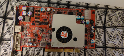
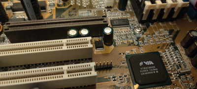
Hello, new on forums, I have same board,gonna need recap alot capacitators, mainly below agp slot, worked sometimes, but not anymore. Gonna Use it with some dos games and windows 98 games. Going to put ati radeon 9800 pro in it, if it works and have some duron cpu, dont have compound so cant check and wont boot.

Attachments

Reply 308 of 346, by dj_pirtu

User metadata
Rank Member
Rank
Member

I have built many retro systems last years and still I think KT7A+Athlon XP-M is the best. Fast enough for newer games and slow enough for older.

My Asus P3B-F+Tualatin 1.4GHz comes close but hard to slow down if needed. But Slot1 helps a lot, takes 1min to swap CPU to say P2 Klamath with unlocked multiplier and then you can get it really slow easily.

Reply 309 of 346, by cde

User metadata
Rank Member
Rank
Member
Kirjoittamaton wrote on 2023-10-03, 06:39:

Hello, new on forums, I have same board,gonna need recap alot capacitators, mainly below agp slot, worked sometimes, but not anymore. Gonna Use it with some dos games and windows 98 games. Going to put ati radeon 9800 pro in it, if it works and have some duron cpu, dont have compound so cant check and wont boot.

Hello and welcome to the forum! Just to say I wish you the best with your recap, it's a lot of work and patience, but 100% worth it 😀

Also, not to diss on ATi cards, but please be sure to give the GeForce 4200 Ti a try (esp. with a Zalman cooler). It works really well in my experience.

Reply 310 of 346, by cde

User metadata
Rank Member
Rank
Member
dj_pirtu wrote on 2023-10-15, 05:18:

I have built many retro systems last years and still I think KT7A+Athlon XP-M is the best. Fast enough for newer games and slow enough for older.

My Asus P3B-F+Tualatin 1.4GHz comes close but hard to slow down if needed. But Slot1 helps a lot, takes 1min to swap CPU to say P2 Klamath with unlocked multiplier and then you can get it really slow easily.

I fully agree dj_pirtu. Really great MB with incredible compatibility and options. A bit finicky to be sure but worth it 😀

Reply 311 of 346, by makechu

User metadata
Rank Newbie
Rank
Newbie
Kirjoittamaton wrote on 2023-10-03, 06:39:

Hello, new on forums, I have same board,gonna need recap alot capacitators, mainly below agp slot, worked sometimes, but not anymore. Gonna Use it with some dos games and windows 98 games. Going to put ati radeon 9800 pro in it, if it works and have some duron cpu, dont have compound so cant check and wont boot.

This might be a bit rant colored regarding recapping in general, but anyways, here goes:
I have recently recapped a KT7A V1.3, which seems to have a with very similar layout. For those three capacitors right next to AGP, the key is to use high temperature tolerating, relatively low ESR (probably around 50 mOhm or less is ok), long-life capacitors as they are connected to the copper areas where the related linear regulator dumps most of its heat output, also heating up the capacitors. It would also be possible to reduce heat stress for the capacitors by leaving their "legs" longer, so that less heat is conducted to the capacitors that way, but unfortunately there is not much space for that...

I recapped everything else on the board as well, but using solid polymer capacitors. Anyways, solid polymer capacitors should not be used for those three under the AGP slot, as solid polymers can't handle above 60+ degree temperatures very well and it can significantly shorten their life spans.

Just as an additional warning; very low ESR polymer capacitors did require also modifying the Chipset / RAM regulator compensation loop to have optimal voltage regulation, so I would not recommend for anyone else to use solid polymers to fully recap the board. Unless, actually understanding electronics well and what other things have to be considered besides changing the capacitors, i.e. ripple rating evaluation, what kind of load each group of capacitors is connected to, check the related regulator IC datasheet and actually understand what is said there, and at least trying to figure out what the original capacitors were and if the new ones are comparable to them, among other things. Just going for some high current, very low ESR capacitors can result in worse stability, unless the all regulator controllers voltage error amplifier feedback compensations loops are adjusted / checked that they are ok with the parallel ESR of the new set of capacitors.

Also, I generally don't recommend anyone to do any kind of full recap of any board, unless they at least know the theory behind switch-mode regulators when those are used on the board. Not to mention that motherboards through hole components are often wave soldered, and getting soldering done properly with a hand held soldering iron can require some extensive experience to know how much heating each soldering point requires to have the proper fill in the through hole channels, i.e. where the capacitor legs go through the board. Also, if anyone ever recaps anything with a non-adjustable cheap crap iron, they need someone to slap them to the back of the head. Maybe it is acceptable for soldering wires, or other non-sensitive stuff, but not PCBs. The only tool to use for any PC electronics is a proper soldering station, unless the goal is to actually just destroy boards...

Finally, having the ESR right matters much less with old boards with linear regulators, but care has to be ALWAYS taken with switch-mode regulators. They are typically optimized for specific types of capacitors with certain ESRs to be used.

Apologies for the rant. I just repaired and recapped a video card that had been previously recapped and almost permanently destroyed by an apparent orangutan and this just came out... Everything was burned with a too hot iron, and some of the pads were missing, including the through hole copper plating from some places. Also, using the wrong technique can destroy the through hole plating, but burning it will cause it to happen very easily.

Last edited by makechu on 2023-10-19, 00:24. Edited 1 time in total.

Reply 312 of 346, by mockingbird

User metadata
Rank Oldbie
Rank
Oldbie
makechu wrote on 2023-10-18, 18:24:

<snip>
Just as an additional warning; very low ESR polymer capacitors did require also modifying the Chipset / RAM regulator compensation loop to have optimal voltage regulation, so I would not recommend for anyone else to use solid polymers to fully recap the board, unless actually understanding electronics well and what other things have to be considered besides changing the capacitors, i.e. ripple rating evaluation, what kind of load each group of capacitors is connected to, etc. Just going for some high current, very low ESR capacitors can result in lowered stability unless the regulator controllers voltage error amplifier feedback compensations loops are adjusted.

Care to provide some detail? I've always wondered about that -- motherboards that are not good polymer candidates -- what exactly are the mechanics involved with that. Show us your work sir!

mslrlv.png
(Decommissioned:)
7ivtic.png

Reply 313 of 346, by BitWrangler

User metadata
Rank l33t++
Rank
l33t++

Here, have a pile of indigestible equations, https://en.wikipedia.org/wiki/RLC_circuit but TL;DR is change resistance even if parasitic resistance, then properties of circuit change.

Unicorn herding operations are proceeding, but all the totes of hens teeth and barrels of rocking horse poop give them plenty of hiding spots.

Reply 314 of 346, by Repo Man11

User metadata
Rank Oldbie
Rank
Oldbie
mockingbird wrote on 2023-10-19, 00:13:
makechu wrote on 2023-10-18, 18:24:

<snip>
Just as an additional warning; very low ESR polymer capacitors did require also modifying the Chipset / RAM regulator compensation loop to have optimal voltage regulation, so I would not recommend for anyone else to use solid polymers to fully recap the board, unless actually understanding electronics well and what other things have to be considered besides changing the capacitors, i.e. ripple rating evaluation, what kind of load each group of capacitors is connected to, etc. Just going for some high current, very low ESR capacitors can result in lowered stability unless the regulator controllers voltage error amplifier feedback compensations loops are adjusted.

Care to provide some detail? I've always wondered about that -- motherboards that are not good polymer candidates -- what exactly are the mechanics involved with that. Show us your work sir!

Here's a link for you. For my 8KRA2+, I ordered Nichicons capacitors that were the same voltage and capacitance as the ones I replaced. It's been three years, and the board still works great.

https://www.overclockers.com/recapping-an-epox-8kra2/

"I'd rather be rich than stupid" - Jack Handey

Reply 315 of 346, by makechu

User metadata
Rank Newbie
Rank
Newbie
mockingbird wrote on 2023-10-19, 00:13:
makechu wrote on 2023-10-18, 18:24:

<snip>
Just as an additional warning; very low ESR polymer capacitors did require also modifying the Chipset / RAM regulator compensation loop to have optimal voltage regulation, so I would not recommend for anyone else to use solid polymers to fully recap the board, unless actually understanding electronics well and what other things have to be considered besides changing the capacitors, i.e. ripple rating evaluation, what kind of load each group of capacitors is connected to, etc. Just going for some high current, very low ESR capacitors can result in lowered stability unless the regulator controllers voltage error amplifier feedback compensations loops are adjusted.

Care to provide some detail? I've always wondered about that -- motherboards that are not good polymer candidates -- what exactly are the mechanics involved with that. Show us your work sir!

I'll have to see if I dare to post how I determined everything when I did the recapping, as I do not actually want anyone to follow in my footsteps with this. Probably better that I just won't do it... Knowledge just increases the pain of the process, as then there is no option to be just satisfied that the system is working, but also knowing that it could somehow be even better. But maybe that is just me...

I wouldn't say polymers are not better than "wet" electrolytic capacitors, performance-wise, as they typically have very good properties to be used in switched mode regulators, and very long life-times, typically 2 - 3 times that of electrolytic capacitors, as long as the capacitor temperatures remain low. However, switching to solid polymer capacitors does require deeper analysis of the regulator circuit as a whole. There are typically pretty straight forward formulas in the regulator IC datasheets that have to be followed when it is determined what values need to be used in the feedback compensation loop, to set the poles and zeros of the compensation / filtering that determine the regulator controller IC's response to what happens in the regulated output voltage. Also, an oscilloscope has to be used, and sometimes the values used in the compensation feedback loop have to be iterated, for which some hints are also given in the datasheets. However, the circuits on the motherboard are not necessarily the same as in the datasheet, and some reverse engineering will be required.

Whenever very low ESR capacitors are used, in most cases the system probably will work, and sometimes maybe even better than with the original capacitors depending on how bad the original capacitors were, i.e. the manufacturer just used bad capacitors to begin with, but the there is the possibility that the voltage regulation is not going to be as good as before, if the regulator IC has been optimized to work with a different kind of behavior by the load it is driving.

But, for anyone without at least some electronics engineering experience / background, I generally would not recommend starting fully recapping anything, unless having strong experience in soldering, proper equipment for PCB rework, and a suitable replacement list provided by a reliable source, as it can actually be somewhat difficult to determine what are the best capacitors to use to have the most optimal results. But sometimes even the suboptimal could be good enough, so that the system will still run ok.

Last edited by makechu on 2023-10-19, 01:09. Edited 1 time in total.

Reply 316 of 346, by mockingbird

User metadata
Rank Oldbie
Rank
Oldbie
makechu wrote on 2023-10-19, 01:02:

I'll have to see if I dare to post how I determined everything when I did the recapping, as I do not actually want anyone to follow in my footsteps with this. Probably better that I just won't do it... Knowledge just increases the pain of the process, as then there is no option to be just satisfied that the system is working, but also knowing that it could somehow be even better. But maybe that is just me...

How about a hint then...? Sure, I'm familiar with the usual warnings of using polymers in a circuit that's not designed for too low an ESR. A good example is old PSUs where the ripple becomes unacceptable when polymers are placed in the secondary filtering circuit. But P4 and later VRMs are almost universally compatible with very low ESR polymers...

Early Athlon VRMs aren't though.

I have another KT7A I want to re-cap, I'd like to get your secret recipe... What was it, the inductors? Did you change the inductors? Couldn't be the MOSFETs, could it?

mslrlv.png
(Decommissioned:)
7ivtic.png

Reply 317 of 346, by makechu

User metadata
Rank Newbie
Rank
Newbie
mockingbird wrote on 2023-10-19, 01:08:
How about a hint then...? Sure, I'm familiar with the usual warnings of using polymers in a circuit that's not designed for too […]
Show full quote
makechu wrote on 2023-10-19, 01:02:

I'll have to see if I dare to post how I determined everything when I did the recapping, as I do not actually want anyone to follow in my footsteps with this. Probably better that I just won't do it... Knowledge just increases the pain of the process, as then there is no option to be just satisfied that the system is working, but also knowing that it could somehow be even better. But maybe that is just me...

How about a hint then...? Sure, I'm familiar with the usual warnings of using polymers in a circuit that's not designed for too low an ESR. A good example is old PSUs where the ripple becomes unacceptable when polymers are placed in the secondary filtering circuit. But P4 and later VRMs are almost universally compatible with very low ESR polymers...

Early Athlon VRMs aren't though.

I have another KT7A I want to re-cap, I'd like to get your secret recipe... What was it, the inductors? Did you change the inductors? Couldn't be the MOSFETs, could it?

It has to be checked from the controller IC datasheets. Some newer regulator ICs have smarter methods of determining required switching adjustments and the use of the external compensation loop is not even required. As an example, in the KT7A, the CPU regulator is more tolerable to using very low ESR capacitors, but the chipset / RAM uses an older regulator IC that requires feedback loop compensation. The CPU regulator uses some sort of a shunt resistor with additional internal logic to implement some sort of "droop" compensation, and I assume the internal logic probably averages the ripple so that the noise components of the signal won't affect the switching of the MOSFETs directly, as it would in older regulator IC designs. Anyways, it is quite late here so I will call it a night here...

Edit: Since I started correcting something from the text, I could give as a hint that I only changed the chipset / RAM regulator's compensation. One ceramic capacitor had to be switched in the loop. Also, only the 1st zero and pole of the filter was implemented in the circuit on the board, and therefore only that can and has to be considered. The main electrolytic capacitors that are connected to the chipset / RAM regulator's output have to be identified, for example with a multimeter, to determine which capacitors are connected to it. I can say that there are 7 electrolytic capacitors, for which the original parallel ESR had to be determined to be able to calculate the required change. By reverse engineering the feedback loop circuit, I determined it was implemented for ~33 mOhms of parallel ESR with the original set of capacitors. My new parallel ESR was significantly lower, and I had to change the capacitor value of C2 = BC13 on the board for the feedback loop to be more towards the correct. The exact values required for the compensation loop will be difficult to determine, as it would require considering any SMD ceramic capacitors in the output as well, which there are too many to start desoldering to determine what they are. However, just using the main capacitor ESRs, I got a regulation result that seemed rock solid on the oscilloscope.
But maybe I said too much already, as like stated, I really don't want anyone to start messing with the tiny compensation loop components. Doing an error there might be able to actually destroy things on the board, and in the expansion slots....

Another edit... Correction to the value of the parallel ESR for the original KT7A chipset / RAM capacitor group; Actually, I estimated the average ESR per electrolytic capacitor to be about 25 - 33 mOhms originally, and the parallel ESR for the whole chipset / RAM capacitor group was only about 3.6 - 3.7 mOhms, which I determined by reverse engineering the feedback compensation circuit.
Well, as an excuce, my memory apparently failed when trying to do a quick reply in the middle of the night...

Last edited by makechu on 2023-10-20, 18:24. Edited 3 times in total.

Reply 318 of 346, by mockingbird

User metadata
Rank Oldbie
Rank
Oldbie
makechu wrote on 2023-10-19, 01:21:

Edit: Since I started correcting something from the text, I could give as a hint that I only changed the chipset / RAM regulator's compensation. One ceramic capacitor had to be switched in the loop. Also, only the 1st zero and pole of the filter was implemented in the circuit on the board, and therefore only that can and has to be considered. The main electrolytic capacitors that are connected to the chipset / RAM regulator's output have to be identified, for example with a multimeter, to determine which capacitors are connected to it. I can say that there are 7 electrolytic capacitors, for which the original parallel ESR had to be determined to be able to calculate the required change. By reverse engineering the feedback loop circuit, I determined it was implemented for ~33 mOhms of parallel capacitance with the original set of capacitors. My new parallel ESR was significantly lower, and I had to change the capacitor value of C2 = BC13 on the board for the feedback loop to be more towards the correct. The exact values required for the compensation loop will be difficult to determine, as it would require considering any SMD ceramic capacitors in the output as well, which there are too many to start desoldering to determine what they are. However, just using the main capacitor ESRs, I got a regulation result that seemed rock solid on the oscilloscope.
But maybe I said too much already, as like stated, I really don't want anyone to start messing with the tiny compensation loop components. Doing an error there might be able to actually destroy things on the board, and in the expansion slots....

Fascinating... I understood it well because you explained it perfectly. Brilliant work, thanks.

mslrlv.png
(Decommissioned:)
7ivtic.png

Reply 319 of 346, by makechu

User metadata
Rank Newbie
Rank
Newbie

I forgot to mention, that the output impedance and stability of the regulator circuit is also affected by other factors as well, besides the capacitors, such as resistive losses, capacitive coupling and mutual inductances between power planes and sensitive traces, and trace inductances, depending on lengths and trace widths to different parts of the circuit. Therefore, the datasheet typically provides a starting point for the feedback compensation design, which may or may not need to be refined further by some empirical testing, depending what is observed in the output voltage at different load levels. As a result, my recommendation is to just use capacitors with similar properties as the original ones, as then the circuit should still behave as it was originally designed for.
Of course, the new capacitors can be more expensive, higher ripple rated and long-life models, but ideally the ESR should closely match the original ones for the circuit to still continue working as originally intended. Otherwise, there must be be considerations of the details mentioned earlier...