VOGONS


First post, by Datadrainer

User metadata
Rank Member
Rank
Member

I have a question about HP Vectra computers from 1993 to 1996.
This machines uses a lot of proprietary connectors. But the one I'm interested in is the CPU FAN connector available on some motherboard from 486 to Pentium (can be present in older 386 machines too)
It is a 5-pin Molex KK connector, but on 1993 to late 1994 the fourth pin is not present.

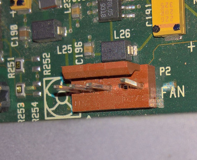
Here is the connector on a 486/66XM:

1.jpg
Filename
1.jpg
File size
302.08 KiB
Views
395 views
File comment
486/66XM fan connector
File license
CC-BY-4.0

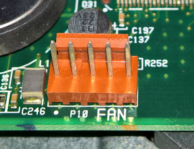
Here it is on a VL/500 (Pentium):

2.jpg
Filename
2.jpg
File size
301.78 KiB
Views
395 views
File comment
VL/500 fan connector
File license
CC-BY-4.0

The pinout for the 486 machines is
pin 1 +12v
pin 2 GND
pin 3 Fan detection (connected to pin 5 through 10 Ω resistor)
pin 4 N/A
pin 5 Fan detection (see pin 3)

I found nothing on the web. pinoutguide.com list the pinout for the connector, but with a different wiring for HP servers. And there is nothing in the doc (HP wasn't prone to deliver any specs of their hardware...)
So what I would like to know is if the 486 connector is pin compatible with the Pentium machine connector, and what is the purpose of the fourth pin (tachometric signal?).
That idea is to document it and because it is near the CPU, I would like to connect the CPU fan here instead of using big 4-pin Molex 8981-4P with 50 cm long wires to get to the first available plug.

If anyone with this knowledge wants to share, I'll be most pleased to access it 😀 Thank you.

Last edited by Stiletto on 2021-09-18, 00:09. Edited 2 times in total.

Knowing things is great. Understanding things is better. Creating things is even better.

Reply 1 of 5, by pentiumspeed

User metadata
Rank l33t
Rank
l33t

When experimenting to bypass the detection. I use 10 to 47 ohms resistors to ground these detection pins. I had to do this to my proliant 1500 and many Dells using 3 pin fan which they do not use tach for this. They ground one pin as long as fan is working but I don't have any dell fans and don't like their choice of dell fans. Ditto to HP in general when I had to learn to ground unused or non-HP connectors using HP boards in generic PC, not just for fans.

Cheers,

Great Northern aka Canada.

Reply 2 of 5, by Datadrainer

User metadata
Rank Member
Rank
Member
pentiumspeed wrote on 2021-09-15, 17:37:

When experimenting to bypass the detection. I use 10 to 47 ohms resistors to ground these detection pins. I had to do this to my proliant 1500 and many Dells using 3 pin fan which they do not use tach for this. They ground one pin as long as fan is working but I don't have any dell fans and don't like their choice of dell fans. Ditto to HP in general when I had to learn to ground unused or non-HP connectors using HP boards in generic PC, not just for fans.

Cheers,

Thank you for your answer.
It is possible bypass the POST detection. But as Overdrive can become hot, I choose to made an adapter from a male 3-pin fan to the plug used by the 486, replacing the original 40x40x20 fan by a Noctua. Very silent now with a stronger airflow and classic fan compatibility in bonus.
But my question isn't to bypass the detection, but what is the fan pinout of a Vectra VL/500 model 515?
I can detect the pin(s) grounded.
Then check the voltage.
If +12V on pin one and pin 2 is grounded, the pin are identical in both machines.
But for the rest....
Maybe there is a way to detect a PWM signal with an oscilloscope and be sure it is that.
But for the pin that are originally bridged (3 and 5), if I try that and it's different, I can create a short circuit and bye bye the computer.

Knowing things is great. Understanding things is better. Creating things is even better.

Reply 3 of 5, by pentiumspeed

User metadata
Rank l33t
Rank
l33t

I said again, your HP does not use PWM to control fan rpm or tach for reading fan speed at all for this vintage.

My compaq Proliant 1500 and Deskpro XL used 4 and 5 pin fan connectors, yet they only used three or four pins and they still used grounded system when fan is working.

What you *will* need is find the correct pin for fan failure detect signal from fan on that motherboard and ground that permanently. Nearly all these vintage computers including Dell using PIII that use more than 3 wires or more will be fan failure signal that is grounded by fan when fan is working. If fan fails, the signal is left floating and this will alert the computer's of a fan failure.

Vintage fans with this type is very hard to find anymore so you like me had to make adapters or rewire the connector correctly when using newer fans.

Cheers,

Great Northern aka Canada.

Reply 4 of 5, by Datadrainer

User metadata
Rank Member
Rank
Member

Hi @pentiumspeed. A lot of time has passed since I opened this thread. A few month ago after having made my measurement I find that and I built an adapter to use a classic fan connector with a 10 ohm resistor to bridge the pins 3 and 5: the fan and the computer are working fine since then. But I still don't know what is the purpose of the 4th pin though as I couldn't get anything from it. The idea of the thread what to identify them all, so maybe someday, someone will tell.
Anyway thank you for your help, it was really helpful 😀

Knowing things is great. Understanding things is better. Creating things is even better.