VOGONS


First post, by Volo

User metadata
Rank Member
Rank
Member

Hello, guys!

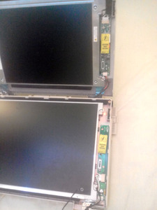
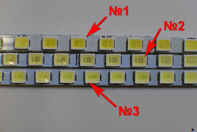
As you might know, I've got two Compaq LTE 5000 laptops:

  • Precious LTE 5000 with 640x680 10.4-inch active TFT;
  • Donor LTE 5380 with 800x600 12.1-inch active TFT.

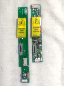
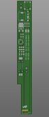
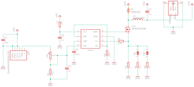
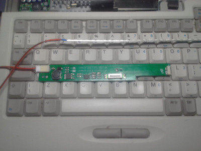
I decided to embark on a journey to create a solderless backlight replacement kit to replace CCFL to LED for those. I’m basing my design on DF6113 chip (popular in Chinese retrofitting kits, datasheet attached). The aim is:

  1. To create direct swap design with no (or optional) soldering needed.
  2. To achieve greater dynamic range: the lowest bigness shall be lower than CCFL, the highest – higher than default maximum;
  3. Stretch goal: the brightness gradient hopefully shall be slightly logarithmic.

Please let me use this thread to document and discuss the project. I plan to disclose the schematics and sell 2-3 leftover conversion kits for a reasonable price, if all goes well.

Attachments

  • Filename
    DF6113-HJH.pdf
    File size
    1.71 MiB
    Downloads
    62 downloads
    File comment
    DF6113 Datasheet
    File license
    Fair use/fair dealing exception
Last edited by Volo on 2021-12-03, 21:54. Edited 1 time in total.

Want to play MS-DOS keyboard-only games with a gamepad? Feel free to purchase Volo's Pad-to-PS/2 by writing me an e-mail:
3hUGsDI.png

Reply 1 of 5, by Volo

User metadata
Rank Member
Rank
Member

So far my achievements are:

I measured the voltages. Those are:

  • Power: 18V (always ON, even if the laptop itself is off!) I don’t know from where the PC steps ups the voltage, but… Ok.
  • “Enable” contact signal: 3,2V. DF6113 datasheet states that it needs exactly that to signal the maximum brightness. I think I’ll use it as control voltage.

I HAVE A PROBLEM THOUGH.
I’ve disassembled both of laptops – the brightness control boards are bloody different (pics attached)! The lager screen has the lamp on the bottom and the smaller – on the top. Also – the smaller board wouldn’t fit the larger screen, as the power wire is not long enough to reach it (See photos attached). The upside is that potentiometer placements and mounting holes are the same. I may still make a “one size fits all” design.

If you may, please help. If you disassembled LTE 5000 screens, please let me know if there is any OTHER PCB design in use? Specifically I am interested in 11.3-inch version.
If you can post the photos of any other control boards - thanks in advance!

Attachments

Want to play MS-DOS keyboard-only games with a gamepad? Feel free to purchase Volo's Pad-to-PS/2 by writing me an e-mail:
3hUGsDI.png

Reply 2 of 5, by Volo

User metadata
Rank Member
Rank
Member

I came up with the scematics (attached, might help someone). Sould work, but I am not sure about resistor values (spesifically R1, R2, R3, R4). I'll ensure those working just by poking currents and voltages. I've gone for 1206 parts - those should be fairly easy to solder.

Stared purchasing and ordered 5 PCBs. Those shall be 1,2mm width, insead of the original 1mm.
The potentiometers are hard to come by. I have to import those from the US for ~4$ each.

Attachments

Want to play MS-DOS keyboard-only games with a gamepad? Feel free to purchase Volo's Pad-to-PS/2 by writing me an e-mail:
3hUGsDI.png

Reply 3 of 5, by Volo

User metadata
Rank Member
Rank
Member

Woah! The bill of materials of 5 kits (including delivery costs and fees) turned out to be US$ 70!
I plan to leave 2 for myself...

Do you mind if I'll offer the remaining 3 kits for US$ 25 a piece just to break even?
I understand that you might opt for one from china for about US$ 7... But please bare in mind, that I plan to offer high-quality LED strips (on alluminium backplane for heat dissapation - option #1 on the photo attached), and the kit shall retain "vanilla" look-and feel (with working brightness slider).

Attachments

  • LEDs.jpg
    Filename
    LEDs.jpg
    File size
    54.1 KiB
    Views
    676 views
    File license
    Fair use/fair dealing exception

Want to play MS-DOS keyboard-only games with a gamepad? Feel free to purchase Volo's Pad-to-PS/2 by writing me an e-mail:
3hUGsDI.png

Reply 4 of 5, by Volo

User metadata
Rank Member
Rank
Member

Situation report:
I have received PCBs and assembled one. Well, I have bad news and good news…

I’ll start with good news:

  1. It works. Not quite as I expected, but it does. The bright light is really bright, the dim light is really dim. No strobe effect – the light is very pleasant. Though does not control the way I expected, but more on that later.
  2. Eyeballing components pretty much paid off – connectors connect and height is flatter than original. It seems that I shouldn’t have invested into $4 pots and may have gotten away with US$ 0.50 apiece. Though I’ll have to redesign the PCB for that.

The bad news are:

  1. I have not resorted to “cardboard mockup” method of fitting the PCB. While it fits into a 12-inch screen, I awfully miscalculated 10-inch screen insides. Have to redo the PCB for that. Now I’ll be sure to fit it in cardboard first.
  2. Brightness control is not good. It’s either “on” or “off” with only a short jittery gradient in the middle. While chip specification states that the brightness is controlled by voltage range of 1.1-3.3V. My measurements state that it is only a 1.9-2.0V. I don’t know if those are “creative” datasheets or my chips are just fake. I’ve read up that other’s people measurements were 1.5-2.5V. Shall have to poke the circuit to find out.
  3. Maximum LED voltage is 10.2 V (unlike expected 9.5V) That may wear-out LEDs a bit: over-10% overvoltage might be an issue.

To-do list:

  1. Circuit-bend the current PCB to see if I can get the desired control regimes from it.
  2. Redesign the PCB to allow cheaper, bulkier parts and to implement fixes, explored by circuit-bending.

Attachments

Want to play MS-DOS keyboard-only games with a gamepad? Feel free to purchase Volo's Pad-to-PS/2 by writing me an e-mail:
3hUGsDI.png

Reply 5 of 5, by RetroTechChris

User metadata
Rank Newbie
Rank
Newbie

Nice! If one of your machines is an LTE 5380, it's actually a 1024x768 screen. I have over a dozen of these and have found that even models of the same series have different LCDs inside (i.e. I have three LTE 5400 series, and they all have different screen manufacturers).

Anyway, we have a group full of knowledge on Facebook and folks there would certainly be interested in your project. Search out "Compaq LTE & Armada Owners" on Facebook if you would like to join. I'm one of the admins there.